
Large-aspect-ratio magnetic shaft structure of shaft type linear motor

A linear motor, large aspect ratio technology, applied in the direction of electrical components, electromechanical devices, electric components, etc., can solve the problems of the complex assembly process of the radially magnetized magnetic steel single body of the ring magnet, and achieve the effect of reducing consumption

Pending Publication Date: 2017-11-03
吴德林
View PDF4 Cites 0 Cited by
  • Summary
  • Abstract
  • Description
  • Claims
  • Application Information

AI Technical Summary

Problems solved by technology

[0005] The technical problem to be solved by the present invention is to provide a magnetic shaft structure with a large length-to-diameter ratio for a shaft-type linear motor. A cross hollow shaft with a special-shaped section is used as the support of the magnetic steel to resist the gravity droop of the magnetic steel shaft; Radial magnetization is carried out on the single-shaped magnet steel, which solves the difficulty of radial magnetization of ring magnets and solves the difficult problem of complex assembly process of magnet steel monomers using axial magnetization, thereby increasing the length-to-diameter ratio of the magnet shaft. Reduced cost and expanded application range of axial linear motors

Method used


Image

  • Large-aspect-ratio magnetic shaft structure of shaft type linear motor
  • Large-aspect-ratio magnetic shaft structure of shaft type linear motor
  • Large-aspect-ratio magnetic shaft structure of shaft type linear motor

Examples


Embodiment 1

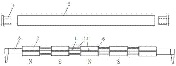
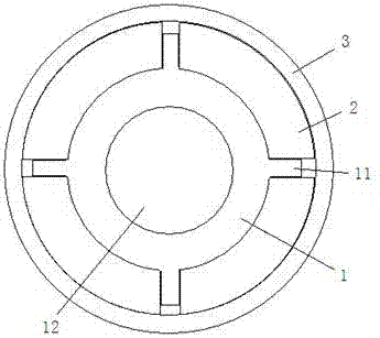
[0026] Such as figure 1 , figure 2As shown, the present invention includes a cross hollow shaft 1, a fan-shaped radial magnetic tile 2, a stainless steel sleeve 3 and an end cover 4. The cross hollow shaft 1 is a symmetrically raised axial rib 11 on the outer peripheral surface of the hollow circular shaft. structure, the outer peripheral surface of the cross hollow shaft 1 is axially connected to the fan-shaped radial magnetic tiles 2 at intervals, and each section is connected by four fan-shaped radial magnetic tiles 2 inner arc walls on the axial peripheral surface between two ribs 11, and the adjacent sections The magnetic tile is a heterogeneous magnetic tile, and the fan-shaped radial magnetic tile 2 is connected into one body and set in the casing 3. The two ends of the hollow cavity of the cross hollow shaft 1 are connected to the water pipe head 5 to form a cooling water channel 12. The water pipe head 5 passes through the end. The cover 3 is snapped and fixed.

...

Embodiment 2

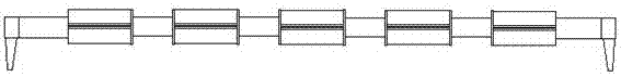
[0030] Such as image 3 As shown, the ribs on the outer peripheral surface of the cross hollow shaft between the two sections of magnetic tiles are removed, and a spacer is connected to the cross hollow shaft at the end of each section of magnetic tile. There is a ring groove, and the ring-shaped spacers are clamped and bonded in the ring groove.


PUM


Abstract

The invention discloses a large-aspect-ratio magnetic shaft structure of a shaft type linear motor. The large-aspect-ratio magnetic shaft structure comprises a cross-shaped hollow shaft, a fan-shaped radial magnetic shoe, a casing and an end cover, wherein the cross-shaped hollow shaft has a longitudinally-symmetrical and bilaterally-symmetrical projecting axial rib structure on an outer peripheral face of a hollow circular shaft; the outer peripheral face of the cross-shaped hollow shaft is axially connected with fan-shaped radial magnetic shoes at intervals; each segment is connected to an axial peripheral face between two ribs through four fan-shaped radial magnetic shoe inner cambered walls; adjacent segments of magnetic shoes are different-stage magnetic shoes; and the cross-shaped hollow shaft and the fan-shaped radial magnetic shoes are connected integrally and sleeved in a casing, and the two ends are meshed and fixed through end covers. The cross-shaped hollow shaft with a special-shaped section is taken as a support of magnetic steel in order to resist gravity fall of a magnetic steel shaft. A shoe-shaped magnetic steel monomer is adopted, and radial magnetization is performed, so that the problems of difficulty in radial magnetization of annular magnetic steel and complex assembly process of an axially-magnetized magnetic steel monomer are solved; the aspect ratio of the magnetic steel shaft is increased; the cost is lowered; and the application range of the shaft type linear motor is enlarged.

Description

technical field [0001] The invention relates to the field of axial linear motors, in particular to a magnetic shaft structure with a large aspect ratio of an axial linear motor. Background technique [0002] The cylindrical shaft linear motor with the solenoid coil as the mover has many advantages: (1) The structure is simple. The cylindrical linear motor can directly produce linear motion without an intermediate conversion mechanism, which greatly simplifies the structure, reduces the motion inertia, and greatly improves the dynamic response performance and positioning accuracy; at the same time, it also improves reliability and saves costs. Easier. Its unique combination of primary and secondary levels that can directly become part of the institution furthers this advantage. (2) Suitable for high-speed linear motion. Because there is no constraint of centrifugal force, ordinary materials can also achieve higher speeds. And if the air cushion or magnetic cushion is used...

Claims


Application Information

Patent Timeline
Patent Type & Authority Applications(China)
IPC IPC(8): H02K41/02
CPCH02K41/02
Inventor 吴德林
Owner 吴德林
Features
  • Generate Ideas
  • Intellectual Property
  • Life Sciences
  • Materials
  • Tech Scout
  • Unparalleled Data Quality
  • Higher Quality Content
  • 60% Fewer Hallucinations
Learn More