MIMO radar waveform design method for neighboring target resolution

A technology of radar waveform and design method, which is applied in the field of MIMO radar, can solve the problems of not being able to effectively take into account high resolution and low-range sidelobe performance, and achieve good practical application value, high computing efficiency, and good sidelobe suppression characteristics.

Active Publication Date: 2017-11-07
THE PLA INFORMATION ENG UNIV
View PDF5 Cites 7 Cited by
  • Summary
  • Abstract
  • Description
  • Claims
  • Application Information

AI Technical Summary

Problems solved by technology

[0003] Aiming at the deficiencies in the prior art, the present invention provides a MIMO radar waveform design method for near target resolution, which solve

Method used


Image

  • MIMO radar waveform design method for neighboring target resolution
  • MIMO radar waveform design method for neighboring target resolution
  • MIMO radar waveform design method for neighboring target resolution

Examples


Example Embodiment

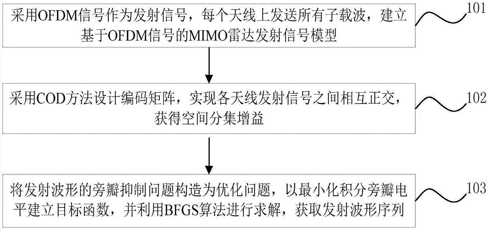
[0050] Embodiment two, see figure 2 As shown, a MIMO radar waveform design method for close target resolution, specifically includes the following steps:

[0051] Step 1: Construct a MIMO radar transmission model based on OFDM signals.

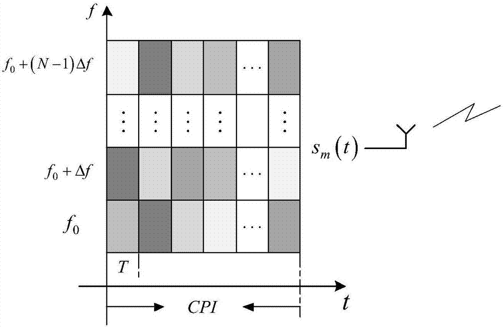
[0052] Suppose the MIMO radar has M transmitting antennas, R X Root receiving antenna. Each antenna transmits Q pulses sequentially within a coherent processing interval (Coherent Processing Interval, CPI), each pulse contains N subcarriers, Represents the OFDM coded sequence on the qth pulse of the mth antenna, where Then the corresponding time domain signal on the pulse is:

[0053] ,

[0054] Among them, T r is the time interval between two adjacent OFDM pulses in a CPI, T is the pulse duration, and the subcarrier interval Δf=1 / T=B / N, the schematic diagram of the transmission signal model of this embodiment is shown in image 3 . Due to the special structure and subcarrier spacing of the OFDM signal itself, an efficient Inverse F...

Example Embodiment

[0098] Embodiment three:

[0099] Simulation conditions:

[0100] Consider the S-band (center frequency f c =3GHz) MIMO radar, assuming that the number of transmitting elements is 4, which is equal to the number of pulses in each CPI, that is, M=Q=4, the number of subcarriers N=300, and the pulse width T=10μs, unless otherwise specified , bandwidth B=30MHz, then the corresponding subcarrier spacing is Δf=0.1MHz. Then the coding matrix after COD design is correspondingly expressed as:

[0101]


PUM


Abstract

The invention belongs to the technical field of MIMO radars, and in particular relates to a MIMO radar waveform design method for neighboring target resolution. The method comprises the steps of firstly, using an OFDM signal as a transmitting signal, transmitting all subcarriers onto each antenna, and then establishing a MIMO radar transmitting signal model based on the OFDM signal; secondly, designing a code matrix by a COD method, and enabling the transmitting signals of each antenna to be mutually orthogonal to obtain the spatial diversity gain; and thirdly, constructing a sidelobe suppression problem of the transmitted waveform as an optimization problem, establishing an objective function by minimizing the integral sidelobe level, and using a BFGS algorithm for a solution to obtain a transmitted waveform sequence. According to the invention, the problem that the MIMO radar cannot balance the high resolution and the low sidelobe in the neighboring target resolution is effectively solved; the modulation and demodulation of the OFDM signals are realized by using the FFT, and the operation efficiency is high; adaptive selection can be allowed according to the actual bandwidth requirement by using the sidelobe suppression algorithm, the flexibility and adaptability of the waveform design method is improved and a good application value is gained.

Description

technical field [0001] The invention belongs to the technical field of MIMO radar, in particular to a MIMO radar waveform design method oriented to resolution of adjacent targets. Background technique [0002] With the continuous improvement of radar range resolution, the resolution of nearby targets has become an important research content of radar systems. The main factors to measure the pros and cons of the close target resolution are the range resolution and the size of the range sidelobe. The waveform diversity and space diversity characteristics of MIMO radar have great advantages in the resolution of nearby targets. However, as the radar working environment becomes increasingly complex, factors such as strong clutter, interference, and multipath will cause higher Range side lobes lead to the problem of submerging weak targets and aliasing of main and side lobes of different targets in the resolution of nearby targets. Therefore, how to design a high-resolution, low-...

Claims


Application Information

Patent Timeline
IPC IPC(8): G01S7/282
Inventor 任修坤柏婷陈松郑娜娥吕品品宋喜玉田英华张靖志张龙
Owner THE PLA INFORMATION ENG UNIV
Why Eureka
Try Eureka