Assembly for dynamically performing optical time domain reflection detection and detection method

An optical time domain reflection and dynamic technology, applied in laser parts, lasers, electrical components, etc., can solve problems such as the inability to meet the needs of convenience and efficiency

Active Publication Date: 2017-11-07
GUANGXUN SCI & TECH WUHAN
View PDF7 Cites 12 Cited by
  • Summary
  • Abstract
  • Description
  • Claims
  • Application Information

AI Technical Summary

Problems solved by technology

However, even for the Raman fiber amplifiers in the C+L band, the existing detection method still uses an independent optical time domain reflectometer for ODTR detection. In a more complex device environment, the existing detection method It is no longer able to meet the needs of convenience and efficiency.

Method used


Image

  • Assembly for dynamically performing optical time domain reflection detection and detection method
  • Assembly for dynamically performing optical time domain reflection detection and detection method
  • Assembly for dynamically performing optical time domain reflection detection and detection method

Examples


Embodiment 1

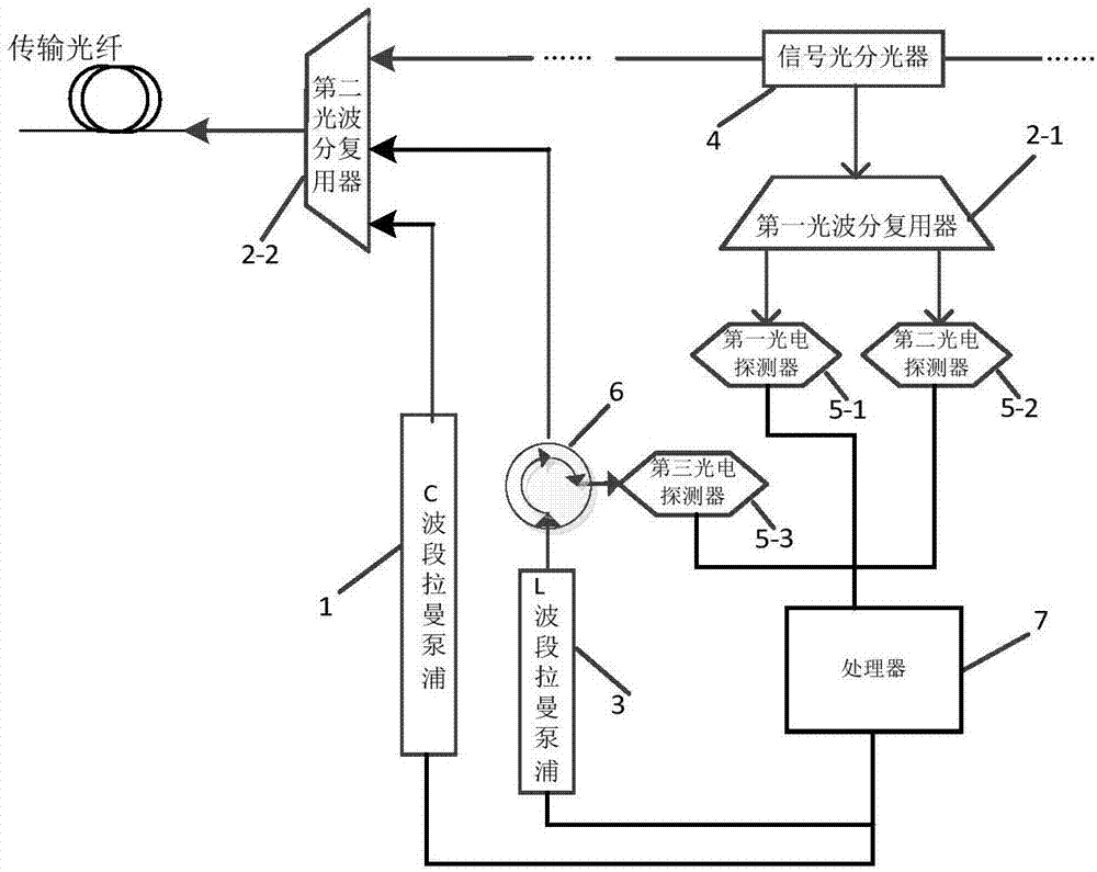
[0092] An embodiment of the present invention provides an optical amplifier component that can dynamically perform optical time domain reflection detection, such as figure 1 As shown, it includes C-band Raman pump 1, L-band Raman pump 3, circulator 6, first optical wavelength division multiplexer 2-1, second optical wavelength division multiplexer 2-2, signal optical splitter 4. The first photodetector 5-1, the second photodetector 5-2, the third photodetector 5-3 and the processor 7, specifically:

[0093] The output port of the L-band Raman pump 3 is connected to the first input end of the circulator 6, and the first output port and the second output port of the circulator 6 are also respectively connected to the second optical wavelength division multiplexer 2 - the second input port of 2 and the third photodetector 5-3, the third input port of the second optical wavelength division multiplexer 2-2 is connected to the C-band Raman pump 1, wherein the first The output port ...

Embodiment 2

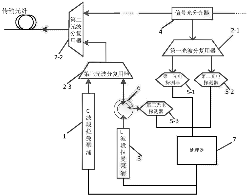
[0114] Embodiment 2 of the present invention provides an optical amplifier component that can dynamically perform optical time domain reflection detection, such as image 3 As shown, it includes C-band Raman pump 1, L-band Raman pump 3, circulator 6, first optical wavelength division multiplexer 2-1, second optical wavelength division multiplexer 2-2, third optical wavelength division multiplexer Multiplexer 2-3, signal light splitter 4, first photodetector 5-1, second photodetector 5-2, third photodetector 5-3 and processor 7, specifically:

[0115] The output port of the L-band Raman pump 3 is connected to the first input end of the circulator 6, and the first output port and the second output port of the circulator 6 are also respectively connected to the third optical wavelength division multiplexer 2 - the second input port of 3 and the third photodetector 5-3, the first input port of the third optical wavelength division multiplexer 2-3 is connected to the C-band Raman p...

Embodiment 3

[0127] Embodiment 2 utilizes the core idea of ​​multiplexing the L-band Raman pump 3 proposed by the present invention, but its optical amplifier component is only one of many possible implementations, and the embodiment of the present invention is also based on the above multiplexing Another optical amplifier component proposed by the core idea of ​​L-band Raman pumping 3 that can dynamically perform optical time-domain reflection detection, such as Figure 4 As shown, it includes a C-band Raman pump first subunit 1-1, a C-band Raman pump second subunit 1-2, an L-band Raman pump 3, a circulator 6, and a first optical wavelength division multiplexing Device 2-1, second optical wavelength division multiplexer 2-2, third optical wavelength division multiplexer 2-3, fourth optical wavelength division multiplexer 2-4, signal optical splitter 4, first photodetector 5 -1, the second photodetector 5-2, the third photodetector 5-3 and the processor 7, specifically:

[0128] The outpu...


PUM


Abstract

The invention relates to the technical field of optical amplifiers, and provides an assembly for dynamically performing optical time domain reflection detection and a detection method. The detection method includes the steps of acquiring signal light intensity detection signals of a first photodetector and a second photodetector, and when confirming that the signal light intensity in the second photodetector is less than a first preset threshold, sending a control signal to an L-band Raman pump so that the L-band Raman pump enters an optical time domain reflection detection mode; and when confirming that the signal light intensity in the second photodetector is greater than or equal to the first preset threshold, sending a control signal to the L-band Raman pump so that the L-band Raman pump enters an L-band Raman fiber amplifier operating mode. According to the invention, the L-band amplified Raman pump laser is made full use of, so that the Raman pump laser can participate in the L-band amplification and can also be used as an OTDR detection optical source, the product function is greatly enhanced, the product design is simplified and the product reuse rate is improved.

Description

【Technical field】 [0001] The invention relates to the technical field of optical amplifiers, in particular to a component and a detection method capable of dynamically performing optical time domain reflection detection. 【Background technique】 [0002] With the continuous development of optical fiber communication in the direction of large capacity and high speed, the topology of optical fiber transmission network becomes more and more complex. In the installation, commissioning, maintenance, upgrade, and overhaul of complex systems, especially in fault diagnosis, it is required to analyze the characteristics of the physical medium of the optical transmission network, determine the nature and location of the fault point in the transmission cable, and quickly take corresponding remedies and maintenance measures. [0003] The core components of the optical time domain reflectometer include a laser and a photodetector. After the laser is pulse-modulated, it emits a certain pow...

Claims


Application Information

Patent Timeline
Patent Type & Authority Applications(China)
IPC IPC(8): H01S3/067H04B10/071
CPCH01S3/06766H01S3/0677H04B10/071H01S3/302H01S3/13013H01S3/0014H01S3/1001H04B10/2916H01S3/094046
Inventor 余振宇卜勤练付成鹏叶知隽刘飞邓福星雷睿蔡潇
Owner GUANGXUN SCI & TECH WUHAN
Why Eureka
Try Eureka