Liquid level detection device circuit board assembly and installation method thereof

A technology of liquid level detection and installation method, which is applied in the direction of buoy liquid level indicators, printed circuit components, laminated printed circuit boards, etc., and can solve problems such as large space occupation, high PCB board hardness, and damage to magnetic induction components

Active Publication Date: 2017-11-07
韩胜池
View PDF16 Cites 2 Cited by
  • Summary
  • Abstract
  • Description
  • Claims
  • Application Information

AI Technical Summary

Problems solved by technology

The carrier for connecting each linear Hall element is a hard PCB printed circuit board, and each Hall element is vertically connected to the PCB printed circuit board. However, the PCB board is relatively hard, which is not conducive to the first Substrates are sheared and are not conducive to the storage of the first su

Method used


Image

  • Liquid level detection device circuit board assembly and installation method thereof
  • Liquid level detection device circuit board assembly and installation method thereof
  • Liquid level detection device circuit board assembly and installation method thereof

Examples


Embodiment 1

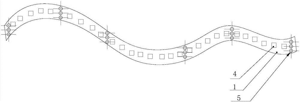
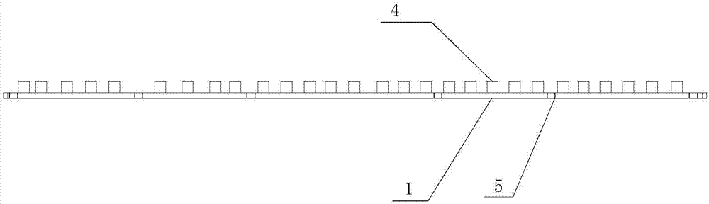
[0075] see Figure 1-Figure 4 As shown, this embodiment provides a circuit board assembly of a liquid level detection device, including a magnetic induction element 4, a first substrate 1, and a second substrate 2. The first substrate 1 is a flexible substrate, and on the first substrate 1 The magnetic induction element 4 is provided; the second substrate 2 is a non-magnetic substrate whose hardness is greater than that of the first substrate 1 , and the first substrate 1 is fixed on the second substrate 2 .

[0076] In the above solution, by arranging the magnetic induction element 4 on the flexible substrate, it is beneficial to roll and store, and facilitates later assembly. The present invention also provides a second substrate 2 with a hardness greater than that of the first substrate 1. The second substrate 2 The tensile strength of the sensor is improved, which is beneficial to the installation and debugging of circuit board components.

[0077]Preferably, the second s...

Embodiment 2

[0105] see figure 1 , figure 2 As shown, this implementation further describes the first substrate 1 on the basis of the first embodiment, the first substrate 1 is a flexible substrate, and the first substrate 1 is provided with a magnetic induction element 4 .

[0106] In the present invention, each magnetic induction element 4 is arranged on the first substrate 1, and the first substrate 1 has many advantages. The magnetic induction element 4 is arranged on the first substrate 1, which is beneficial to storage. For example, the first substrate 1 can be wound It is not necessary to use a hard printed circuit board as the substrate of the magnetic induction element 4 as in the prior art, so that the formed detection circuit is inconvenient to store and prone to wear and tear. On the other hand, in this embodiment, the first substrate 1 is used as the carrier of the magnetic induction element 4 , which is beneficial for cutting the first substrate 1 during the assembly proce...

Embodiment 3

[0116] This embodiment provides a method for installing a circuit board assembly applied to the liquid level detection device in Embodiment 1, including the following steps:

[0117] S1. Cutting the first substrate 1 of the required length according to the process requirements;

[0118] S2. Cutting the second substrate 2 according to the length of the first substrate 1;

[0119] S3, bonding and fixing the first substrate 1 and the second substrate 2 through the third substrate 3;

[0120] S4. Put sealing sleeves 6 on each of the fixed substrates for encapsulation.

[0121] In the above step S1, the length of the first substrate 1 is cut according to the length required by the liquid level inspection device.

[0122] Preferably, in step S2, the second substrate 2 is cut to be longer than the first substrate 1, and a reserved section is formed at one end thereof for later connection and fixing with a corresponding installation structure to define the position of the circuit boar...


PUM


Abstract

A liquid level detection device circuit board assembly disclosed by the present invention comprises a magnetic induction element, a first substrate and a second substrate, the first substrate is a flexible substrate, and a magnetic induction element is arranged on the first substrate. The second substrate is a nonmagnetic substrate, the hardness of the second substrate is greater than that of the first substrate, and the first substrate is fixed on the second substrate. According to the present invention, the magnetic induction element is arranged on the flexible substrate, thereby facilitating winding and storing, and being convenient for the later assembly. The present invention simultaneously provides the second substrate of which the hardness is greater than that of the first substrate, and the second substrate enables the tensile strength of a sensor to be improved, thereby facilitating installing and debugging the circuit board assembly. The present invention also discloses an installation method of the circuit board assembly simultaneously. The first substrate and the second substrate are connected fixedly via a third substrate having a buffer effect, thereby preventing the first substrate from being stressed and damaged. The method is simple and practical, and enables the installation efficiency and the installation quality of the circuit board assembly to be improved.

Description

technical field [0001] The invention relates to the technical field of liquid level sensors, in particular to a circuit board assembly of a liquid level detection device and an installation method thereof. Background technique [0002] At present, most of the existing float level sensors are reed switch float sensors. Several reed switches are installed in the detection tube of the sensor. When the float floats up and down along the detection tube with the liquid level, different The reed switch at the position acts, so that the resistance value output by the sensor changes, and the controller converts the changed resistance value into other signals for display to the user. [0003] The utility model patent with the application number of 91216416.6 discloses a reed switch type float liquid level sensor, which is composed of a float, a float, a permanent magnet and N groups of reed switches, and each group of reed switches is placed and welded in the horizontal direction On ...

Claims


Application Information

Patent Timeline
IPC IPC(8): H05K1/02H05K1/18H05K3/00H05K5/06G01F23/30
CPCG01F23/30H05K1/0281H05K1/189H05K3/0058H05K5/06H05K2201/10151
Inventor 韩胜池
Owner 韩胜池
Why Eureka
Try Eureka