Linear compressor and manufacturing method thereof

A linear compressor and surface treatment technology, applied in mechanical equipment, engine components, engine parameters, etc., can solve the problems of high manufacturing cost of linear compressors, piston wear, high cost, etc., to simplify the surface treatment process and prevent performance. The effect of reducing and preventing clogging

Active Publication Date: 2020-06-19
LG ELECTRONICS INC
View PDF12 Cites 0 Cited by
  • Summary
  • Abstract
  • Description
  • Claims
  • Application Information

AI Technical Summary

Problems solved by technology

[0024] Therefore, in the case of manufacturing a linear compressor using the manufacturing method of the prior document 2, the first process is performed after the outer shape of the piston is manufactured, and then it is packaged and transferred to a company for the second process at a cost of logistics. Therefore, there are inconveniences in actual operation
Furthermore, the first process requires relatively high costs
As a result, there is a problem that the manufacturing cost of the linear compressor becomes high
[0025] In addition, according to the manufacturing method of the prior document 2, after the first process is performed, a step of grinding the surface of the buffer portion with a relatively large roughness is required, so that the manufacturing cost is correspondingly increased. If there is a defect in the grinding process, the desired surface treatment performance of the piston cannot be achieved
[0026] If the surface treatment performance of the piston is not well realized, in the drive of the linear compressor, especially when the initial start-up of the linear compressor cannot fully exert the performance of the gas bearing, there will be a gap between the piston and the cylinder. friction, which causes the piston to be worn

Method used


Image

  • Linear compressor and manufacturing method thereof
  • Linear compressor and manufacturing method thereof
  • Linear compressor and manufacturing method thereof

Examples


Embodiment Construction

[0069] Hereinafter, specific embodiments of the present invention will be described with reference to the drawings. However, the technical idea of ​​the present invention is not limited to the disclosed embodiments, and those skilled in the art who understand the technical idea of ​​the present invention can easily suggest other embodiments within the scope of the same technical idea.

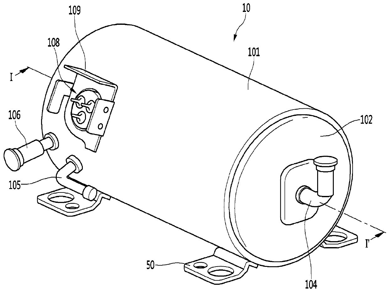
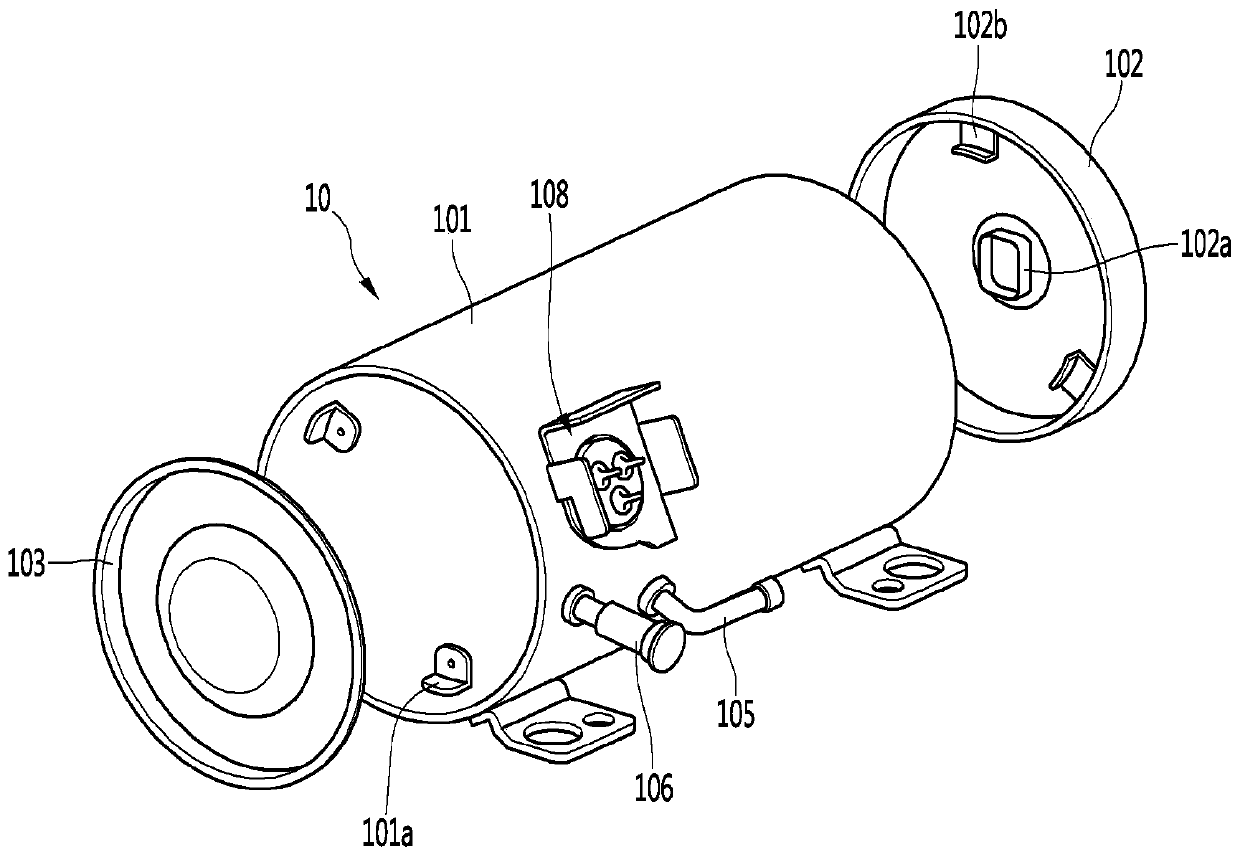
[0070] figure 1 is an external perspective view showing the structure of a linear compressor according to an embodiment of the present invention, figure 2 It is an exploded perspective view of a housing and a housing cover of the linear compressor according to the embodiment of the present invention.

[0071] refer to figure 1 and figure 2 , The linear compressor 10 of the embodiment of the present invention includes: a housing 101 ; and housing covers 102 , 103 combined with the housing 101 . In a broad sense, the first housing cover 102 and the second housing cover 103 can be understood...


PUM

PropertyMeasurementUnit
thicknessaaaaaaaaaa
thicknessaaaaaaaaaa
strengthaaaaaaaaaa

Abstract

The present invention provides a linear compressor and a manufacturing method thereof. The linear compressor of the embodiment of the present invention includes: a piston inserted into a cylinder and reciprocating; the piston includes: a surface-treated body made of aluminum or an aluminum alloy; The first surface treatment part is arranged on the outside of the surface treatment body by a first vacuum evaporation method; and the second surface treatment part is arranged on the outside of the first surface treatment part by a second vacuum evaporation method.

Description

technical field [0001] The present invention relates to a linear compressor and a method of manufacturing the same. Background technique [0002] The cooling system refers to a system in which a refrigerant circulates and generates cold air, which repeatedly performs compression, condensation, expansion, and evaporation processes of the refrigerant. To this end, the cooling system includes: a compressor, a condenser, an expansion device and an evaporator. In addition, the cooling system may be installed in a refrigerator or an air conditioner as a home appliance. [0003] Generally speaking, a compressor (Compressor) is a mechanical device that receives power transmitted from a power generating device such as an electric motor or a turbine, and compresses air or refrigerant or other working gases to increase its pressure. Compressors are widely used in such household appliances or in the entire industrial field. [0004] Such compressors can be roughly divided into recipr...

Claims


Application Information

Patent Timeline
Patent Type & Authority Patents(China)
IPC IPC(8): F04B39/00F04B35/04C23C14/06C23C16/27
CPCC23C14/0641C23C16/278F04B35/04F04B39/0005F04B2203/04F04B35/045F04B39/1073F04B39/121F04B39/123F16J1/01C23C14/34C23C16/26C23C16/505C23C28/042C23C28/044C23C28/046C25D11/02F04B39/10C23C14/14C23C16/27C23C16/50C23C28/32C23C28/343F04B27/0878F04B39/0016F04B39/0276F04B39/12F04B53/14F05C2201/021F05C2251/10F05C2253/12
Inventor 李敬源金烔汉金秉柱禹炳勋郑圆铉
Owner LG ELECTRONICS INC
Why Eureka
Try Eureka