Evaporator for wastewater evaporation

An evaporator and waste water technology, applied in water/sewage treatment, chemical instruments and methods, water/sludge/sewage treatment, etc., can solve the problems of poor waste water treatment effect, failure to meet waste water treatment standards, etc., and achieve low resistance Effect

Pending Publication Date: 2017-11-17
哈尔滨电气环保有限公司
View PDF11 Cites 3 Cited by
  • Summary
  • Abstract
  • Description
  • Claims
  • Application Information

AI Technical Summary

Problems solved by technology

[0004] The purpose of the present invention is to solve the problem that the waste water treatment effect of the existing desulfurization system is poor and cannot meet the waste water treatment standard, and further provide an evaporator for waste water evaporation

Method used


Image

  • Evaporator for wastewater evaporation
  • Evaporator for wastewater evaporation
  • Evaporator for wastewater evaporation

Examples


specific Embodiment approach 1

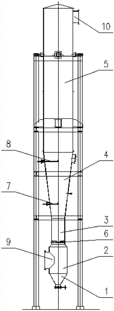
[0025] Specific implementation mode one: combine Figure 1-Figure 4 Describe this embodiment. An evaporator for wastewater evaporation in this embodiment includes an evaporator ash hopper 1, an evaporator inlet section 2, a constriction transition section 3, a cone barrel expansion section 4, an evaporation section 5, and a swirl rectifier 6. The first-stage dual-fluid spray gun 7 and the second-stage dual-fluid spray gun 8, the side of the evaporator inlet section 2 is provided with an air inlet flue 9, and the lower end of the evaporator inlet section 2 is connected to the evaporator ash hopper 1, The upper end of the inlet section 2 of the evaporator is connected to the necking transition section 3, the upper end of the necking transition section 3 is connected to the cone barrel expansion section 4, and the upper end of the cone barrel expansion section 4 is connected to the evaporation section 5, and the evaporation section 5 The top side of the top is provided with an ou...

specific Embodiment approach 2

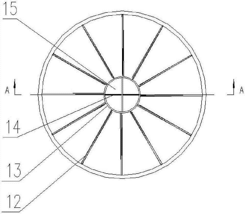
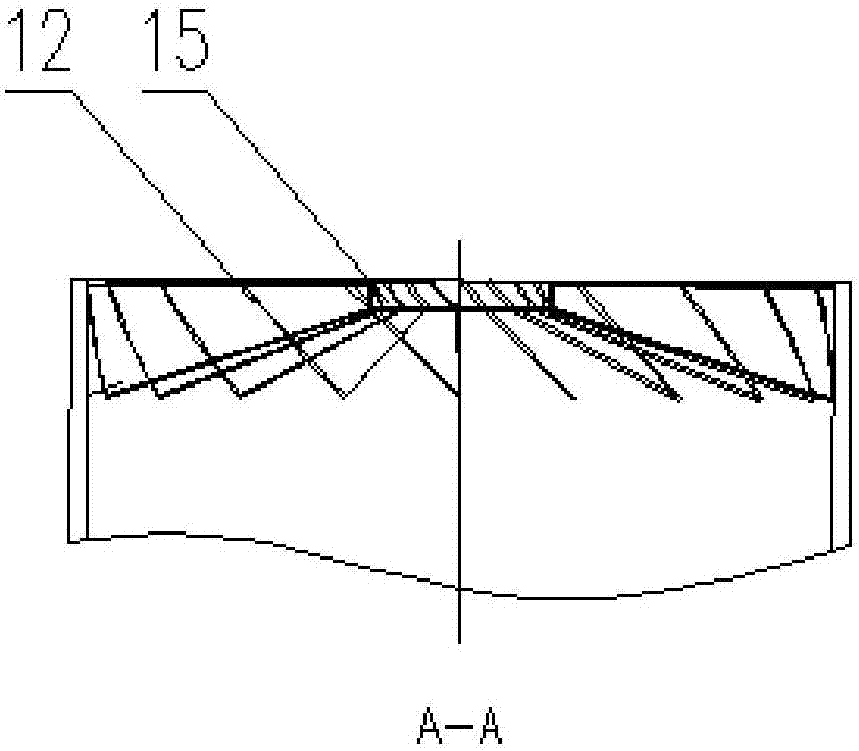
[0027] Specific implementation mode two: combination Figure 1-Figure 3 To illustrate this embodiment, the swirl rectifier 6 described in an evaporator for evaporating waste water in this embodiment is arranged at the entrance of the constricted transition section 3, and the swirl rectifier 6 is arranged to cover the entrance of the constricted transition section 3. Section; the swirl rectifier 6 includes rectifying blades 12, a rectifier central cylinder 13, a cross rib 14 and a central cylinder cover plate 15, and the rectifier central cylinder 13 is arranged at the entrance center of the necking transition section 3, and the rectifier The central cylinder 13 is supported and fixed by cross ribs 14 , the rectifying vanes 12 are evenly distributed along the circumference of the rectifier central cylinder 13 , and the upper and lower ends of the rectifier central cylinder 13 are closed by the central cylinder cover plate 15 . In this way, the flue gas enters the initial stage ...

specific Embodiment approach 3

[0028] Specific implementation mode three: combination figure 1 To illustrate this embodiment, the constricted transition section 3 of the evaporator for evaporating wastewater in this embodiment is a cylindrical structure, and the diameter of the constricted transition section 3 is smaller than the diameter of the inlet section 2 of the evaporator. In this way, the flow rate of the flue gas in the constricted transition section 3 is accelerated compared with that in the evaporator inlet section 2, and the diameter of the constricted transition section 3 is smaller than that of the evaporator inlet section 2, which is convenient for compressing the flue gas, and is convenient for the expansion section of the cone barrel. 4 connections.

[0029] Specific implementation mode four: combination figure 2 Describe this embodiment, the rectifying blades 12 described in an evaporator for wastewater evaporation in this embodiment are evenly distributed along the circumference around ...


PUM


Abstract

The invention provides an evaporator for wastewater evaporation and belongs to the technical field of wastewater evaporation treatment. The evaporator aims to solve the problem that an existing desulfurization system is poor in wastewater treatment effect and cannot meet the wastewater treatment standard. The device comprises an evaporator ash bucket, an evaporator inlet section, a necking transition section, a conical barrel expansion section, an evaporation section and a rotational flow rectifier, wherein the side face of the evaporator inlet section is provided with an air inlet flue, the lower end of the evaporator inlet section is connected with the evaporator ash bucket, the upper end of the evaporator inlet section is connected with the necking transition section, the upper end of the necking transition section is connected with the conical barrel expansion section, the evaporation section is connected with the upper end of the conical barrel expansion section, an outlet flue is arranged on the side face of the top of the evaporation section, and the rotational flow rectifier is installed in the necking transition section. According to the evaporator, desulfurization wastewater is evaporated into solid particles and water, and the evaporation treatment of the desulfurization wastewater is achieved.

Description

technical field [0001] The invention relates to a waste water evaporator, which belongs to the technical field of waste water evaporation treatment. Background technique [0002] During the operation of wet flue gas desulfurization devices in thermal power plants, a certain amount of wastewater will be produced. The waste water generated in the wet desulfurization process of boiler flue gas (limestone / gypsum method) comes from the discharge water of the absorption tower. To improve the quality of gypsum, a certain amount of waste water must be discharged from the system, and the waste water mainly comes from the gypsum dehydration and cleaning system. [0003] At present, the desulfurization wastewater treatment process mainly deals with the first and second types of pollutants, and the main process methods used are physical and chemical methods. The process flow is a scaled model based on the application of desulfurization wastewater treatment process in power plants abro...

Claims


Application Information

Patent Timeline
Patent Type & Authority Applications(China)
IPC IPC(8): C02F1/12C02F1/16
CPCC02F1/043C02F1/048C02F1/12C02F1/16
Inventor 杨维本程旺斌孙晶柳杨李小宇
Owner 哈尔滨电气环保有限公司
Why Eureka
Try Eureka