Metal oxide/NiPi photo-anode material and preparation thereof

A technology of oxide and photoanode, applied in electrodes, electrolysis process, energy input, etc., to achieve the effect of improving photocurrent density and hole injection efficiency, improving charge transfer, and low energy consumption

Active Publication Date: 2017-11-17
SHANTOU UNIV
View PDF3 Cites 3 Cited by
  • Summary
  • Abstract
  • Description
  • Claims
  • Application Information

AI Technical Summary

Problems solved by technology

[0004] The object of the present invention is to provide a kind of metal oxide / NiPi photoanode material and preparation thereof to solve existing problems

Method used


Image

  • Metal oxide/NiPi photo-anode material and preparation thereof
  • Metal oxide/NiPi photo-anode material and preparation thereof
  • Metal oxide/NiPi photo-anode material and preparation thereof

Examples


Embodiment 1

[0039] A kind of Fe2O3 / NiPi photoanode preparation method is as follows:

[0040] (1) Preparation of FeOOH nanorod film on FTO: the formula is: 0.15M FeCl3: 0 ~ 1M NaNO3 (adjusting pH to 1.3 ~ 2) hydrothermal reaction solution is placed in the inner tank with FTO, the inner tank Seal it in an autoclave, conduct a hydrothermal reaction at 70-110° C. for 3-10 hours, wash, and dry to form a layer of light yellow transparent FeOOH nanorod film. Increasing the hydrothermal reaction time resulted in larger FeOOH nanorods.

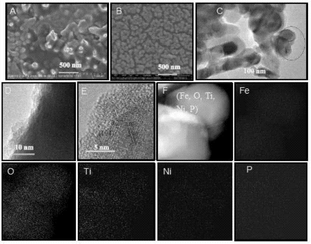
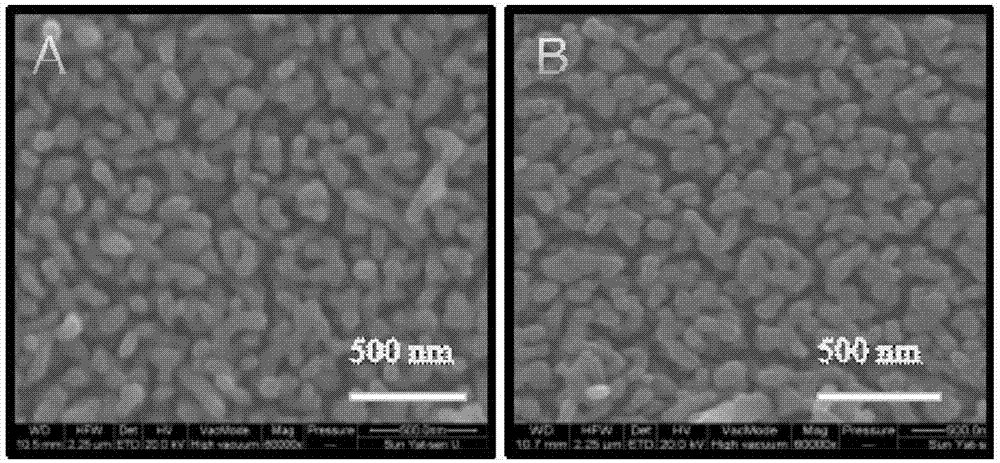
[0041] (2) Fe 2 o 3 Film preparation: the above-mentioned FeOOH film is placed in a tube furnace and calcined for 20-120 minutes when the temperature is raised to 500-750°C, cooled to room temperature and taken out to obtain red-red Fe2O3 and electrodes, the appearance of which is as follows: figure 1 A shows.

[0042] from figure 2 A can see Fe 2 o 3 The Fe 2p3 / 2 and 2p1 / 2 of the film are located at 710.4eV and 723.7 eV, respectively, which are Fe 2 o ...

Embodiment 2

[0051] a kind of Fe 2 o 3 / NiPi photoanode is prepared as follows:

[0052] (1) Preparation of 0-5% Ti:FeOOH nanorod film on FTO: the formula is: 0.15M FeCl 3 : 0~1MNaNO 3 : 0 ~ 7.5mM Ti solution (such as K 2 TiF 6 、TiCl 3 、TiCl 4 , TiCN, TiF 4 etc.) (adjust the pH to 1.3~2) hydrothermal reaction solution is placed in the liner equipped with FTO, seal the liner in the autoclave, perform hydrothermal reaction at 70-110°C for 3-10 hours, wash and dry , forming a layer of light yellow transparent 0-5% Ti:FeOOH nanorod film. Increasing the hydrothermal reaction time will result in larger size 0-5%Ti:FeOOH nanorods.

[0053] (2) 0~5%Ti:Fe 2 o 3 Film preparation: the above-mentioned 0-5% Ti:FeOOH film is placed in a tube furnace and calcined for 20-120 minutes when the temperature is raised to 500-750°C, cooled to room temperature and taken out to obtain red-red 0-5% Ti:Fe 2 o 3 electrodes, which look like figure 1 Shown in B. Such as figure 2 As shown in A and 2B, ...


PUM

PropertyMeasurementUnit
thicknessaaaaaaaaaa
diameteraaaaaaaaaa

Abstract

The invention relates to a metal oxide / NiPi photo-anode material which comprises a metal oxide photo-anode and a NiPi thin film passivation layer, wherein a NiPi thin film is wrapped on the outer side of the metal oxide photo-anode. The preparation method comprises the following steps: (1) preparing a metal oxide photo-anode film; (2) dropwise coating the metal oxide photo-anode film with Ni salt and a neutral phosphate buffer solution, and performing deposition to prepare a NaNiPO4 thin film; and (3) performing photoelectric chemical regulation and control on the metal oxide photo-anode / NaNiPO4 thin film. According to the metal oxide / NiPi photo-anode material, Ti is doped into the surface of pure Fe2O3, so that a rich oxygen vacancy is introduced, which provides an assistance to improvement of conductivity; the NiPi wrapping layer inhibits the surface state of the pure Fe2O3; the NiPi wrapping layer has performance of inhibiting reaction of conduction band electrons and oxygen, so that surface charge transferring of an Fe2O3 electrode is enhanced comprehensively; with a lower oxygen evolution overpotential, the NiPi thin film is an extremely good substitute for CoPi in the aspect of catalytic water decomposition; meanwhile, the metal oxide / NiPi photo-anode material is easy to operate; and a Ni-containing catalyst is prepared at room temperature, so that energy consumption is low, and the operation time is short.

Description

technical field [0001] The invention belongs to the field of photoelectrochemical anodes, in particular to a metal oxide / NiPi photoanode material and its preparation. Background technique [0002] Photoelectrolysis of water is considered to be a clean way to produce hydrogen and oxygen. For the photoelectrochemical anode, there are two basic requirements. The first is to have a low oxygen production onset potential, and the second is to have better working stability to reduce oxidation and dissolution during work. Among them, α-Fe 2 o 3 (abbreviated as Fe 2 o 3 ) The theoretical maximum photogenerated current density reaches 12.6mA / cm 2 , can meet the needs of industry (10mA / cm 2 ). However, Fe 2 o 3 The electrode bulk phase charge separation efficiency is low, and the surface hole injection (catalyzed water oxidation) efficiency is low. CoPi and IrO 2 cladding is the most used to reduce the Fe 2 o 3 Water Oxidation Onset Potential (Angew.Chem.Int.Ed., 49(2010)6...

Claims


Application Information

Patent Timeline
Patent Type & Authority Applications(China)
IPC IPC(8): C25B11/06C25B1/04
CPCC25B1/04C25B1/55C25B11/051C25B11/055C25B11/091Y02E60/36Y02P20/133
Inventor 高文华王建陈耀文鲁福身
Owner SHANTOU UNIV
Why Eureka
Try Eureka