
Machining center tool decision making method for low-carbon manufacturing

A technology of machining centers and decision-making methods, used in manufacturing computing systems, genetic laws, predictions, etc.

Active Publication Date: 2017-11-21
XI AN JIAOTONG UNIV
View PDF3 Cites 9 Cited by
  • Summary
  • Abstract
  • Description
  • Claims
  • Application Information

AI Technical Summary

Problems solved by technology

The present invention is aimed at the processing environment of a single machining center, and can solve the specific problems in the following two aspects: (1) organize and manage the limited cutting tools on the production site in consideration of the remaining life; (2) use the cutting tools from the perspective of production cost and production carbon emission Plan to make decisions, and finally obtain the workpiece to be processed in each section and the required loading tool information

Method used


Image

  • Machining center tool decision making method for low-carbon manufacturing
  • Machining center tool decision making method for low-carbon manufacturing
  • Machining center tool decision making method for low-carbon manufacturing

Examples


Embodiment

[0164] The technical solutions of the present invention will be described below in conjunction with specific examples.

[0165] A batch of processing tasks containing 10 workpieces is assigned to a machining center for processing. Table 1 shows the specific information of this batch of workpieces. There are 6 types of tools used to process this batch of workpieces at the production site, and the available tool information is shown in Table 2.

[0166] Table 1 Processing task information table

[0167] Work No.

[0168] Table 2 Available Tool Information Table

[0169]

[0170] The following takes the working step 1 of the workpiece 1 as an example to illustrate the calculation process of the machining capacity of the available tool types in the working step. The machining allowance of work step 1 of workpiece 1 is:

[0171] Workpiece diameter D: 60mm; processing length L: 150mm; processing allowance Δ: 8mm.

[0172] It can be processed with tool type d1, and i...


PUM


Abstract

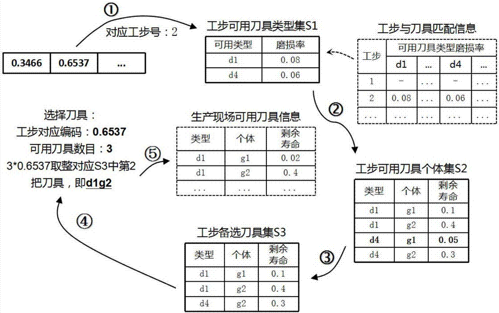
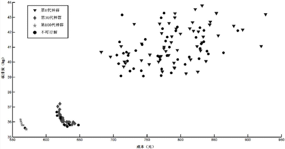
The present invention relates to a machining center tool decision making method for low-carbon manufacturing, which is applied to a single machining center manufacturing system. The method comprises the specific steps of: 1. determining the remaining life of each tool; 2. determining the available tool type and the corresponding cutting parameter for each work step of each workpiece; 3. calculating the processing time, processing power and tool wear rate of the available tool type for each work step in sequence, and obtaining a work step-tool type matching table; 4. using the multi-objective genetic algorithm considering tool life constraint to solve the problem, calculating the production cost and the carbon emission under different tool usage schemes and workpiece processing orders to obtain the optimal chromosome; 5. based on the optimal chromosome information, obtaining the processing tool of each work step and the loading tool set of each processing section, and putting them into production. The method according to the invention can make a quick decision on the choice and the loading order of the tools on the production site, generate the processing scheme where the cost and the carbon emission are optimized and coordinated, and guide the tool preparation and actual production.

Description

technical field [0001] The invention belongs to the technical field of low-carbon manufacturing and intelligent manufacturing, and in particular relates to a low-carbon manufacturing-oriented cutting tool decision-making method for a machining center. Background technique [0002] With the increasingly prominent problems of high energy consumption and high emissions in the manufacturing industry, low-carbon manufacturing has gradually attracted attention as the main direction of industrial transformation. The low-carbon manufacturing system includes many aspects such as product design methods, manufacturing and processing techniques, and parts recycling. The mechanical processing process is a key link in the manufacturing process, and the optimal use of energy and carbon emission control in the processing process is an indispensable part of the low-carbon manufacturing system. [0003] In the modern manufacturing process, the machining center greatly saves the time of the a...

Claims


Application Information

Patent Timeline
IPC IPC(8): G06Q10/04G06Q10/06G06Q50/04G06N3/12
CPCG06N3/126G06Q10/04G06Q10/0637G06Q50/04Y02P90/30Y02P90/82Y02P90/84
Inventor 周光辉傅祥璟张超元晟泽田长乐
Owner XI AN JIAOTONG UNIV
Learn More