Cutting and falling device for chip packing pipe

A blanking device and packaging tube technology, which is applied in metal processing and other directions, can solve the problems of chip packaging tube mouth deformation and chipping, chip packaging tubes are prone to chipping, and production efficiency is low, so as to avoid chipping and deformation , smooth cross-section, and the effect of improving production efficiency

Active Publication Date: 2017-11-24
池州华宇电子科技股份有限公司
View PDF7 Cites 2 Cited by
  • Summary
  • Abstract
  • Description
  • Claims
  • Application Information

AI Technical Summary

Problems solved by technology

When the existing chip packaging tubes are pulled and cut, manual retrieving is often used, that is, the operator collects the cut chip packaging tubes, which is not only labor-intensive, but also low in production efficiency. The speed is fast and there is a large residual stress. Therefore, when the chip is cut directly, the chip packaging tube is prone to defects such as chipping. It is easy to cause the nozzle of the chip packaging tube to deform and collapse

Method used


Image

  • Cutting and falling device for chip packing pipe
  • Cutting and falling device for chip packing pipe
  • Cutting and falling device for chip packing pipe

Examples


Embodiment Construction

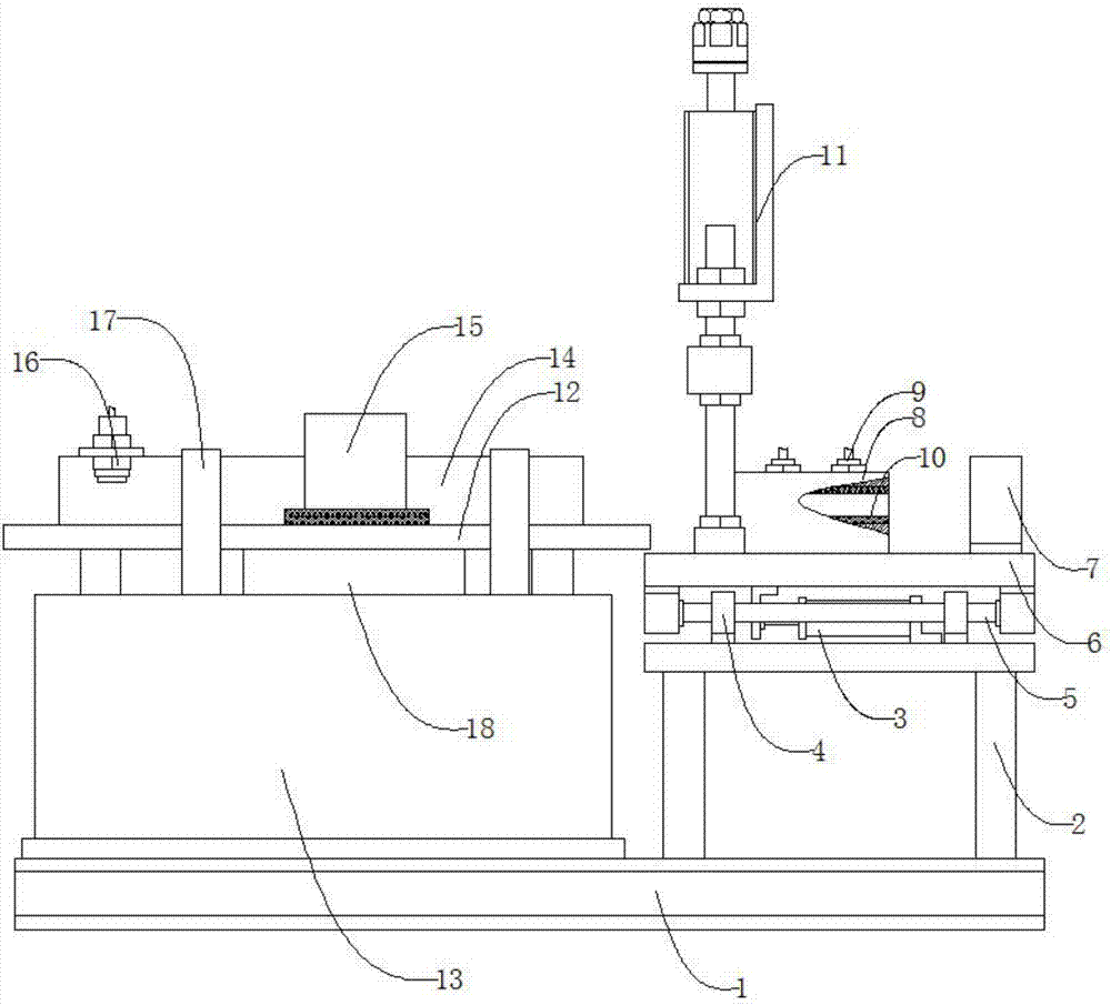
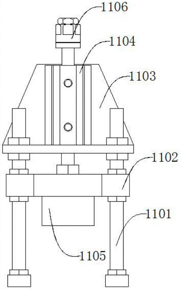
[0037] Such as figure 1 , figure 2 , image 3 , Figure 4 , Figure 5 , Figure 6As shown, a chip packaging tube cutting and blanking device includes a base 1, a right table 2, a feeding cylinder 3, a guide seat 4 symmetrically arranged along the right table 2, a guide rod 5, and a supporting plate 6 , limit seat 7, aluminum mold 8, heating tube 9, copper sleeve 10, cutting mechanism 11, left workbench 12, material box 13, adjustment seat 14, pushing mechanism 15, photoelectric sensor 16, retaining strip 17, guide Material plate 18, the right side table 2 is located on the right side of the upper end of the base 1, the right side table 2 is threadedly connected with the base 1, the delivery cylinder 3 is located at the upper end of the right table 2, the The feeding cylinder 3 is threadedly connected with the right table 2, the guide seat 4 is located at the upper end of the right table 2, the guide seat 4 is threaded with the right table 2, and the guide rod 5 runs thro...


PUM


Abstract

The invention discloses a cutting and falling device for a chip packing pipe. The cutting and falling device comprises a base, a right side working table, a sending-in air cylinder, a guiding seat, a guiding rod, a supporting plate, a limiting seat, an aluminum mould, a heating pipe, a copper sleeve, a cutting mechanism, a left side working table, a material box, an adjusting seat, a material pushing mechanism, a photoelectric sensor, a blocking strip and a material guiding plate, wherein the guiding seat, the guiding rod, the supporting plate, the limiting seat, the aluminum mould, the heating pipe, the copper sleeve, the cutting mechanism, the left side working table, the material box, the adjusting seat, the material pushing mechanism, the photoelectric sensor, the blocking strip and the material guiding plate are distributed symmetrically along the right side working table. The heating pipe works to heat chip packing pipes, so that stress is relieved; when the chip packing pipes trigger the photoelectric sensor, the cutting mechanism works to cut the chip packing pipes; because the chip packing pipes are sent to a machine continuously, the follow-up chip packing pipes are prevented from moving left by the cutting mechanism, so that deformation of the follow-up chip packing pipes is caused; the sending-in air cylinder pushes the supporting plate to move left, so that the cutting mechanism is driven to move left; and the sending-in air cylinder resets after the cutting mechanism resets, so that deformation of the follow-up chip packing pipes can be removed, opening cracking is prevented, then the material pushing mechanism pushes the cut chip packing pipes to falling into the material box, so that cutting and falling are completed.

Description

technical field [0001] The invention relates to a mechanical device, in particular to a chip packaging tube cutting and blanking device. Background technique [0002] The material of the chip packaging tube is usually PVC, and its function is to hold the packaged IC chip. Its production process is: mix PVC resin, stabilizer, lubricant, colorant, and filler, and heat it at the same time. , through the extrusion of the twin-screw extruder into the die of the head, so as to extrude a soft tubular product, and then through a series of processes such as vacuum sizing, vacuum cooling, laser marking, traction cutting, etc., to make a pipe. When the existing chip packaging tubes are pulled and cut, manual retrieving is often used, that is, the operator collects the cut chip packaging tubes, which is not only labor-intensive, but also low in production efficiency. The speed is fast and there is a large residual stress. Therefore, when the chip is cut directly, the chip packaging tub...

Claims


Application Information

Patent Timeline
Patent Type & Authority Applications(China)
IPC IPC(8): B26D1/60B26D7/10B26D5/12B26D7/32
CPCB26D1/60B26D5/12B26D7/10B26D7/32Y02P70/10
Inventor 陶高松赵从寿张友位彭勇韩彦召周根强
Owner 池州华宇电子科技股份有限公司
Why Eureka
Try Eureka