Direct injection type gas/liquid fuel supply system of rotary engine and control method of direct injection type gas/liquid fuel supply system

A technology of fuel supply system and rotary engine, which is applied in engine control, electrical control, engine components, etc., can solve the problems of substandard emissions and low efficiency of rotary engines, and achieve the solution of substandard emissions, expand multi-fuel characteristics, and solve efficiency low effect

Inactive Publication Date: 2017-11-24
JIANGSU UNIV
View PDF9 Cites 14 Cited by
  • Summary
  • Abstract
  • Description
  • Claims
  • Application Information

AI Technical Summary

Problems solved by technology

[0004] Aiming at the deficiencies in the prior art, the present invention provides a gas / liquid fuel supply system and control method for a direct-injection rotary engine, which can precisely control the injection strategy of gas and liquid fuel and the ignition strategy of the spark plug to rationally organize the mixture The formation and reliable ignition of the rotary engine can solve the problems of low efficiency and substandard emissions of the rotary engine, and fully expand the multi-fuel characteristics of the rotary engine, which is conducive to the improvement of the performance of the rotary engine

Method used


Image

  • Direct injection type gas/liquid fuel supply system of rotary engine and control method of direct injection type gas/liquid fuel supply system
  • Direct injection type gas/liquid fuel supply system of rotary engine and control method of direct injection type gas/liquid fuel supply system
  • Direct injection type gas/liquid fuel supply system of rotary engine and control method of direct injection type gas/liquid fuel supply system

Examples


Embodiment 1

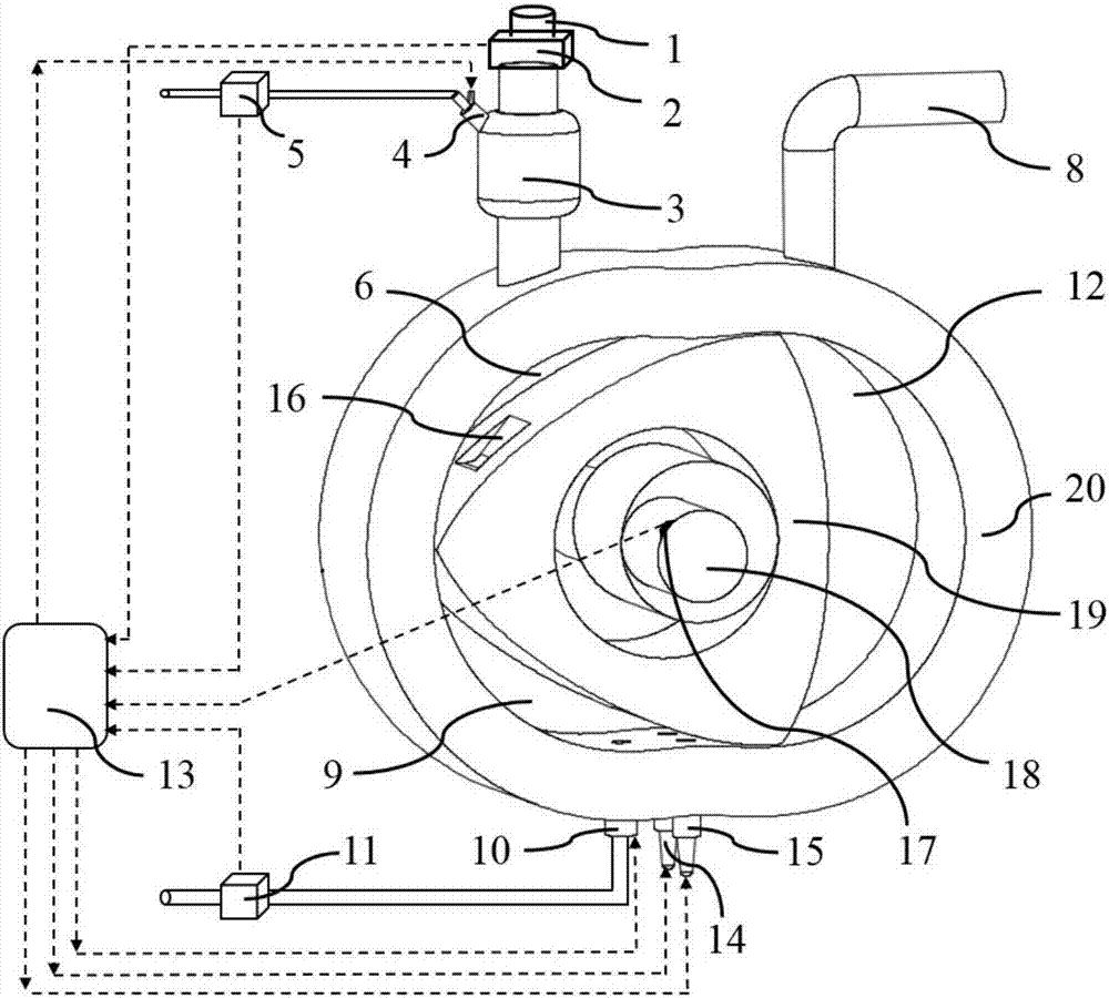
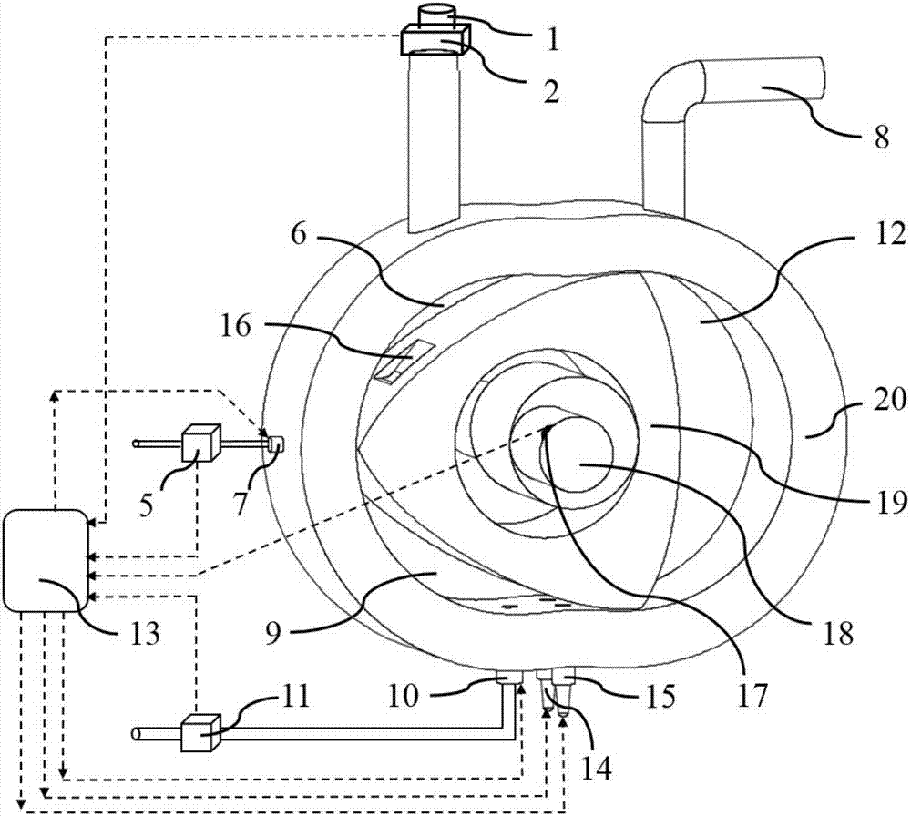
[0043] In Embodiment 1 and Embodiment 2, the gas ejected from the first gas fuel nozzle 4 or the second gas fuel nozzle 7 is biogas or natural gas or hydrogen or petroleum gas; the liquid gasoline ejected from the liquid fuel nozzle 10 or Diesel or kerosene or jet fuel or biodiesel or heavy fuel oil.

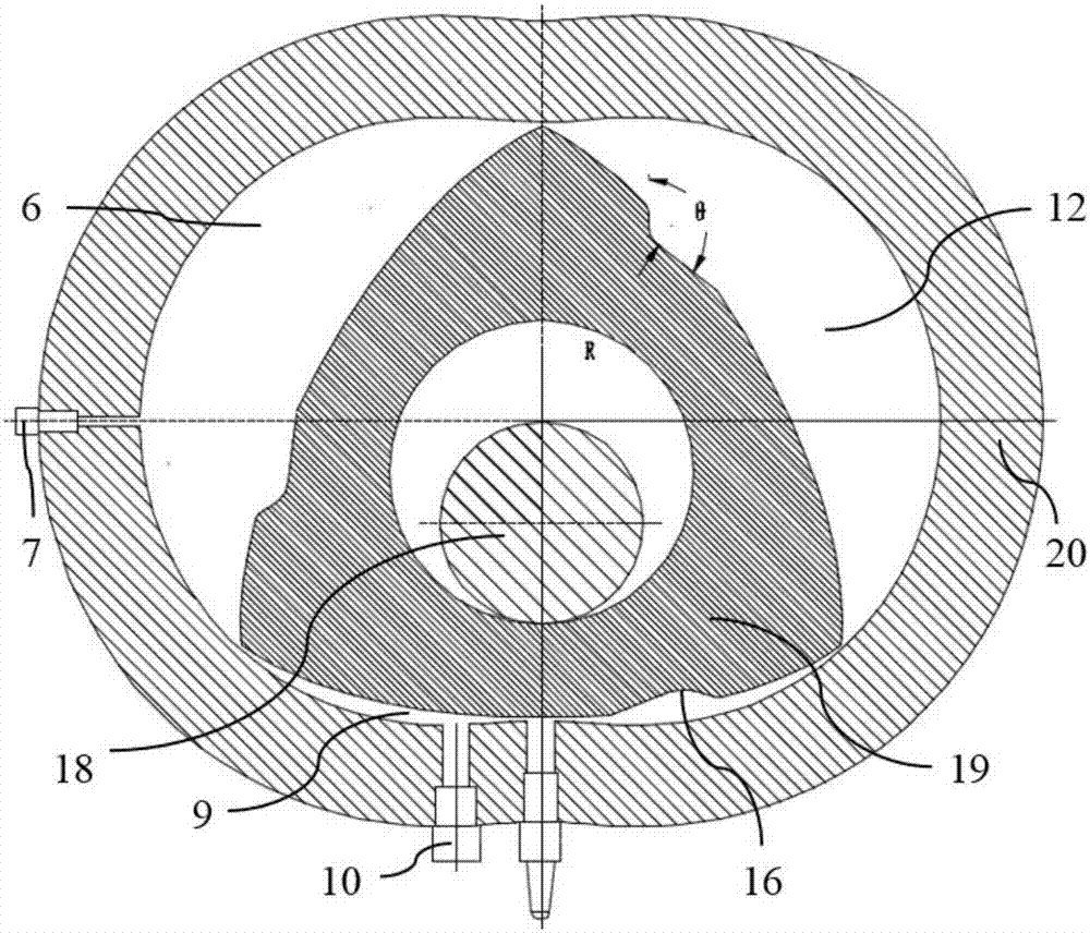
[0044] Such as image 3 As shown, the outer surface of the triangular rotor 19 is provided with dimples 16; the cross-section of the dimples 16 is approximately triangular. The pit 16 and the outer surface of the triangular rotor 19 have a circular arc transition with a radius of 8-10mm; the included angle θ of the outline of the pit 16 is 120°-128°. The purpose is to ensure that the high-speed injected fuel collides and diffuses at the pit 16, so that the fuel is mostly concentrated in the middle and front of the combustion chamber, which is beneficial to subsequent combustion work and power output. The angle between the injection direction of the first gas fuel nozzle 4 and ...


PUM


Abstract

The invention provides a direct injection type gas / liquid fuel supply system of a rotary engine. The direct injection type gas / liquid fuel supply system comprises the rotary engine, a gas injection system, a liquid injection system and an electronic control unit (ECU). The rotary engine comprises a cylinder, combustors and a triangular rotor, wherein the combustors are located between the cylinder and the triangular rotor, and the cylinder is internally provided with an exhaust pipe which communicates with the third combustor. The liquid injection system comprises a liquid fuel nozzle and a sparking plug, the liquid fuel nozzle is arranged on the cylinder and communicates with the second combustor, and the second combustor is internally provided with the sparking plug. The gas injection system comprises a second gas fuel nozzle, and the second gas fuel nozzle is arranged on the cylinder and communicates with the first combustor. The ECU is connected with the sparking plug, the liquid fuel nozzle, a revolution speed transducer and the second gas fuel nozzle. The direct injection type gas / liquid fuel supply system can accurately control the injection strategy of gas fuel and liquid fuel and the ignition strategy of the sparking plug to reasonably recognize formation and reliable ignition of mixed gas.

Description

technical field [0001] The invention relates to the field of internal combustion engines, in particular to a gas / liquid fuel supply system and a control method of a direct-injection rotary engine. Background technique [0002] Compared with the reciprocating piston engine, the rotary engine has the characteristics of simple structure, high power density, low noise, low vibration, and excellent high-speed performance. Especially its outstanding multi-fuel performance has attracted widespread attention. At present, for a rotary engine that only burns a single fuel, due to the law of flame propagation from the rear to the front, the combustible mixture at the rear of the combustion chamber cannot be completely combusted, resulting in low combustion efficiency and poor emission performance. It is well known that gaseous fuel has a faster flame propagation velocity in the combustion process, and liquid fuel blended with gaseous fuel can effectively increase the combustion rate o...

Claims


Application Information

Patent Timeline
Patent Type & Authority Applications(China)
IPC IPC(8): F02B53/00F02B53/10F02B53/02F02B55/02F02D43/00F02D19/08F02P15/02
CPCF02B53/00F02B53/02F02B53/10F02B55/02F02D19/081F02D37/02F02D2200/04F02D2200/06F02D2200/0611F02P15/02Y02T10/12
Inventor 陈伟潘剑锋潘振华刘杨先范宝伟
Owner JIANGSU UNIV
Why Eureka
Try Eureka