Binary-code-to-thermometer-code circuit
A thermometer code and binary code technology, applied in thermometers, thermometers using electrical/magnetic components directly sensitive to heat, using electrical devices, etc. The effect of small transmission delay, reduced chip area and simple circuit structure
- Summary
- Abstract
- Description
- Claims
- Application Information
AI Technical Summary
Problems solved by technology
Method used
Image

Examples
Embodiment 1
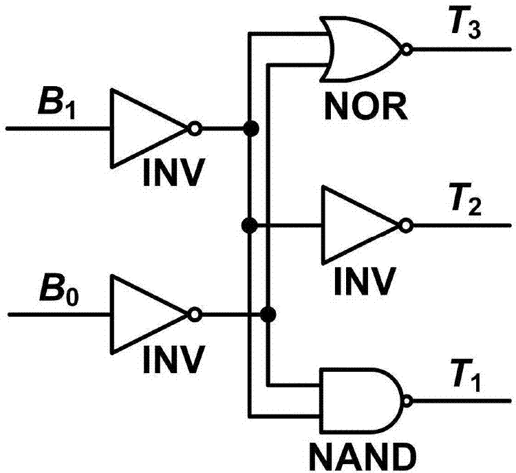
[0027] see image 3 : the binary code conversion thermometer code circuit of the present embodiment includes a 2-wire-3-wire structure, and the 2-wire-3-wire structure includes an inverter INV1, a transmission gate Tg 1 , transmission gate Tg 2 , transmission gate Tg 3 , NMOS tube Mn1, PMOS tube Mp1, the input is binary code B 1 and binary code B 0 , the output is the thermometer code T 3 , thermometer code T 2 , thermometer code T 1 ; The input of the inverter INV1 is binary code B 1 , output its inversion signal Bv 1 ; The transmission gate Tg 2It is in the normally-on state, which is used to reduce the delay difference of the signal on different transmission paths, and the transmission gate Tg 1 and transmission gate Tg 3 B 0 As input, the output is respectively connected to the thermometer code T 1 and thermometer code T 3 , the transmission gate Tg 1 and transmission gate Tg 3 The phase of the control signal is opposite, the transmission gate Tg 1 The non-...
Embodiment 2
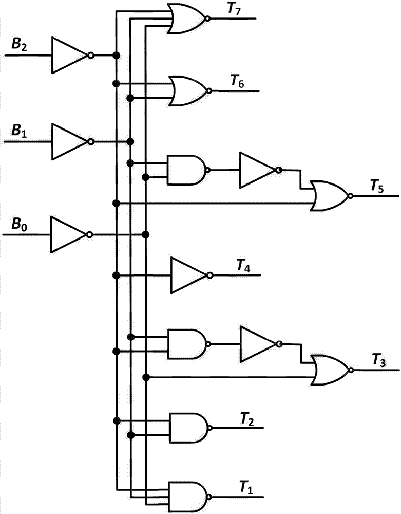
[0029] see Figure 4 : The binary code conversion thermometer code circuit of the present embodiment is a 3-7 wire circuit, and the 3-7 wire circuit is divided into two parts of the front cascade I and the rear cascade II; the front cascade I is a 2-wire-4 line structure, the 2-wire-4-wire structure is composed of the 2-wire-3-wire structure in Embodiment 1, the inverter INV2 and the transmission gate Tg 4 Composition; the 2-wire-3-wire structure input is binary code B 1 and B 0 , the output is the thermometer code T 11 , thermometer code T 21 and thermometer code T 31 ; The input of the inverter INV2 is binary code B 2 , output its inversion signal Bv 2 ; The transmission gate Tg 4 It is normally on state, Tg 4 The input is the binary code B 2 , output B 21 Connected to Rear Cascade II. The post-cascade II consists of a transmission gate Tg 42 And the module circuits B1, B2, B3, C5, C6 and C7 with selection function are formed; the transmission gate Tg 42 is norm...
PUM
 Abstract
Description
Claims
Application Information
 - R&D
- Intellectual Property
- Life Sciences
- Materials
- Tech Scout
- Unparalleled Data Quality
- Higher Quality Content
- 60% Fewer Hallucinations
Browse by: Latest US Patents, China's latest patents, Technical Efficacy Thesaurus, Application Domain, Technology Topic, Popular Technical Reports.
© 2025 PatSnap. All rights reserved.Legal|Privacy policy|Modern Slavery Act Transparency Statement|Sitemap|About US| Contact US: help@patsnap.com