Periodic oscillation laser welding method and welding assembly

A technology of laser welding and periodic oscillation, applied in laser welding equipment, welding equipment, metal processing equipment, etc., can solve the problems of uneconomical, low utilization rate of galvanometer, low moving speed and response speed of worktable, etc., to achieve easy welding , High efficiency and fast welding speed

Inactive Publication Date: 2017-12-01
HANS LASER TECH IND GRP CO LTD
View PDF6 Cites 19 Cited by
  • Summary
  • Abstract
  • Description
  • Claims
  • Application Information

AI Technical Summary

Problems solved by technology

[0002] In the new energy industry, large-scale sheet metal industry, etc., for some applications with wide welds or curved welds caused by workpiece processing and assembly errors, welding thermal deformation, etc., if the traditional vibrating head is used, the spot is small and requires a spot Multiple reciprocating moveme

Method used


Image

  • Periodic oscillation laser welding method and welding assembly
  • Periodic oscillation laser welding method and welding assembly
  • Periodic oscillation laser welding method and welding assembly

Examples


Embodiment 1

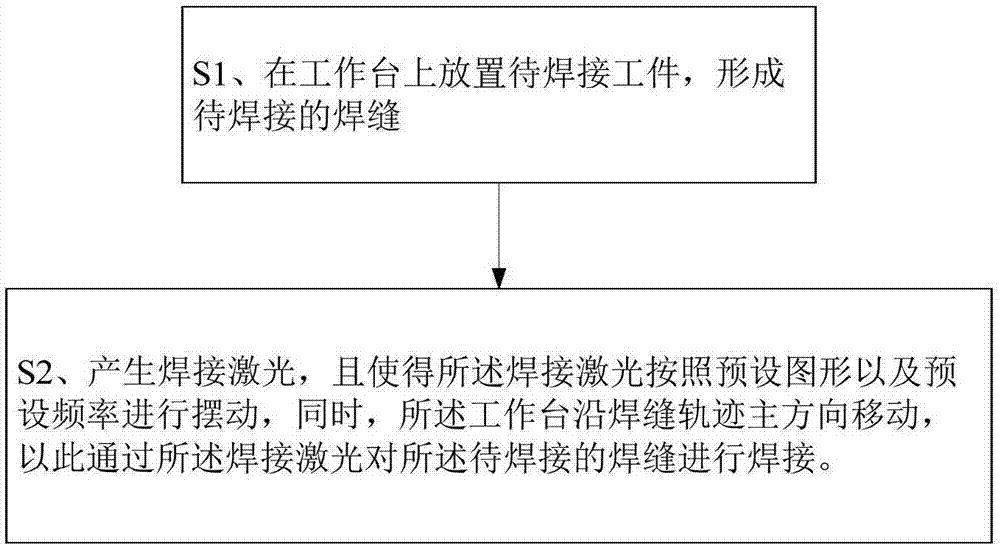
[0043] Figure 1-8b It shows a flow chart of the steps of the periodic oscillating laser welding method of the present invention and a schematic diagram of welding, which includes the following steps:

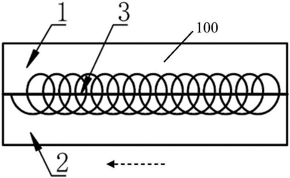
[0044] S1. Place workpieces 1 and 2 to be welded (such as 6061 alloy, etc.) on the workbench 100 to form a weld 3 to be welded;

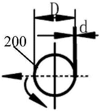
[0045] S2. Generate a welding laser (the welding laser can be generated by swinging a laser welding head, etc.), and make the welding laser oscillate according to a preset pattern 200 and a preset frequency (according to Figure 2b , 3b, 4b, 5b, 6b and 7b in the direction indicated by the solid arrow to complete the preset graphics), at the same time, the workbench is along the main direction of the weld track to be welded (ie Figures 2a-8b In the direction indicated by the dotted arrow in the center), the welding seam to be welded is welded by the welding laser.

[0046] Further, in the step S2, the preset graphics include regular or irregular gr...

Embodiment 2

[0053] The present invention also provides a welding assembly for realizing the above-mentioned welding method, which includes:

[0054] Workbench, which is used to carry workpieces to be welded;

[0055] An oscillating laser welding head, which is used to generate a welding laser, and make the welding laser oscillate according to a preset pattern and a preset frequency;

[0056] And a moving component, which is used to move the worktable along the main direction of the welding seam trajectory.

[0057] Preferably, the welding assembly also includes:

[0058] The control device has a control program, which is used to control the movement of the oscillating laser welding head along the track of the welding seam to be welded, so as to compensate the deviation of the welding seam in the curve or broken line welding seam in positive and negative directions.

[0059] As shown in Figures 9-12, in the welding method and welding assembly of the present invention, the laser spot emit...


PUM


Abstract

The invention discloses a periodic oscillation laser welding method and a welding assembly. The method comprises the following steps that firstly, a to-be-welded workpiece is placed on a workbench, and a to-be-welded welding line is formed; and secondly, a welding laser is generated, the welding laser swings according to the preset pattern and the preset frequency, meanwhile, the workbench moves in the welding line track main direction, and the welding laser is used for welding the to-be-welded welding line. Light spots of the welding laser periodically swing with the small amplitude and at high speed according to the preset pattern, meanwhile, the workbench moves in the welding line direction, accordingly, a wide welding line and a curve welding line can be easily welded, the welding speed is high, and efficiency is high.

Description

technical field [0001] The invention relates to the field of laser welding, in particular to a periodic oscillation laser welding method and a welding assembly. Background technique [0002] In the new energy industry, large-scale sheet metal industry, etc., for some applications with wide welds or curved welds caused by workpiece processing and assembly errors, welding thermal deformation, etc., if the traditional vibrating head is used, the spot is small and requires a spot Multiple reciprocating movements along the weld seam for multiple welding, the utilization rate of the galvanometer is low, and it is uneconomical; if a collimating and focusing single head is used for welding with the movement of the worktable, the moving speed and response speed of the worktable are low, which seriously restricts the welding efficiency. [0003] Therefore, it is necessary to provide a welding method that can easily weld wide weld seams and curved weld seams, and has high welding speed...

Claims


Application Information

Patent Timeline
IPC IPC(8): B23K26/21B23K26/08B23K26/044
CPCB23K26/21B23K26/044B23K26/08
Inventor 邬全兵谢泽楷曹锋王瑾高云峰
Owner HANS LASER TECH IND GRP CO LTD
Why Eureka
Try Eureka