Bionic double-shaft hair sensor device

A sensor device, silicon micro-sensor technology, applied in the direction of measuring devices, instruments, gyroscopes/steering sensing equipment, etc., can solve the problems of multi-physical signal sensitivity, single physical quantity, and single function, so as to improve detection sensitivity and accuracy , Strong anti-interference ability, and the effect of suppressing swing motion

Active Publication Date: 2017-12-01
SOUTHEAST UNIV
View PDF14 Cites 17 Cited by
  • Summary
  • Abstract
  • Description
  • Claims
  • Application Information

AI Technical Summary

Problems solved by technology

However, at present, the bionic hair sensors developed by most institutions can only be sensitive to a single physical quanti

Method used


Image

  • Bionic double-shaft hair sensor device
  • Bionic double-shaft hair sensor device
  • Bionic double-shaft hair sensor device

Examples


Embodiment 1

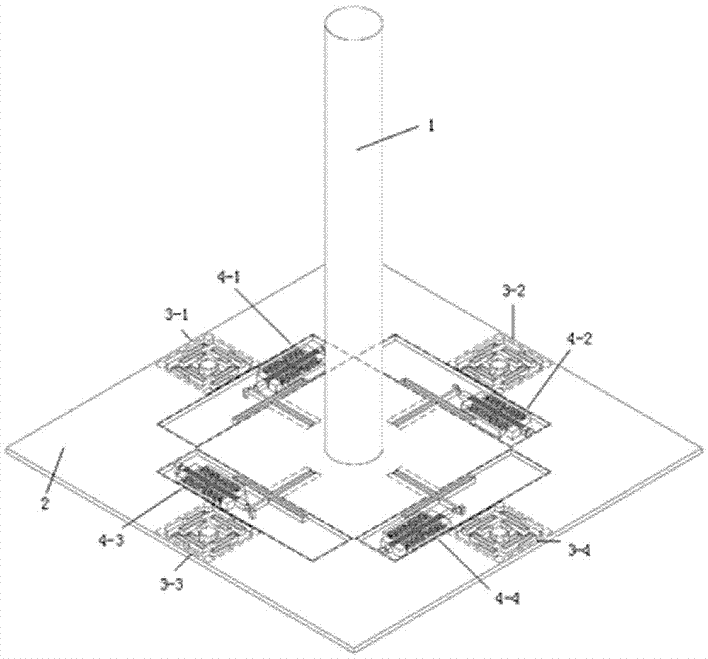
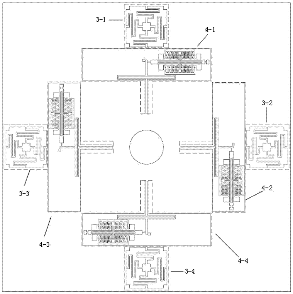
[0034] Such as Figure 1 ~ Figure 2 As shown, the present invention provides a bionic biaxial hair sensor device, comprising a three-layer structure consisting of an upper layer of metal aluminum alloy hair 1, a middle layer of silicon micro sensors, and a lower layer of a glass substrate with signal leads. The metal aluminum alloy The hair is glued to the center position of the upper surface of the silicon micro sensor, the silicon micro sensor is composed of a base mass 2, four swing suppression elastic structures and four resonator substructures, the four resonator substructures are respectively located on the base In the hollow area on the four sides of the mass 2, the four swing suppression elastic structures are respectively located in the hollow areas on the sides of the four resonator substructures, and the four swing suppression elastic structures and the four resonator substructures all pass through the anchor points. Bonded to a glass substrate on which signal leads a...

Embodiment 2

[0036] The first swing restraining elastic structure 3-1, the second swing restraining elastic structure 3-2, the third swing restraining elastic structure 3-3, and the fourth swing restraining elastic structure 3-4 have exactly the same structure and the adjacent interval is 90 Degree, specifically taking the first swing restraining elastic structure 3-1 as an example, such as Figure 4 As shown, the first swing suppression elastic structure 3-1 is composed of a first square wave elastic beam 3-1a, a second square wave elastic beam 3-1b, a third wave elastic beam 3-1c, and a fourth square wave elastic beam 3-1d. One end of the first square wave elastic beam 3-1a is connected to the base mass 2 and the other end is connected to the anchor point 5-1. The first square wave elastic beam 3-1a is located at the anchor The upper side of point 5-1; one end of the second square wave elastic beam 3-1b is connected to the base mass 2, and the other end is connected to the anchor point 5-1...

Embodiment 3

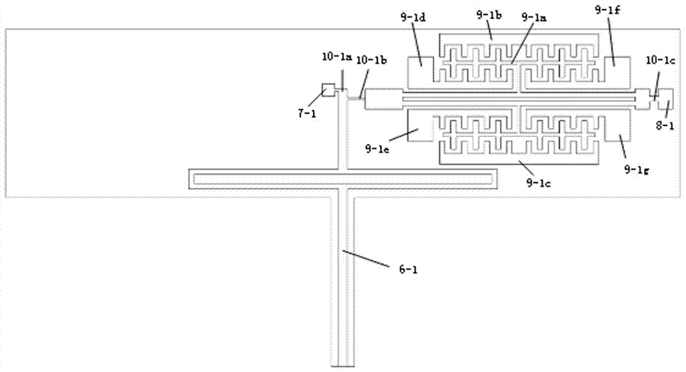
[0038] The first resonator sub-structure 4-1, the second resonator sub-structure 4-2, the third resonator sub-structure 4-3 and the fourth resonator sub-structure 4-4 have exactly the same structure and the adjacent interval is 90 Degree, such as image 3 As shown, specifically taking the first resonator sub-structure 4-1 as an example, the first resonator sub-structure 4-1 consists of a first lever elastic beam 6-1, a first double-ended fixed tuning fork and its driving detection comb. The structure 9-1 is composed of a first double-ended fixed tuning fork and its drive detection comb structure 9-1 consisting of a first double-ended fixed tuning fork 9-1a containing comb teeth, a first drive comb 9-1b, and a The two driving comb teeth 9-1c and the first detecting comb teeth 9-1d, the second detecting comb teeth 9-1e, the third detecting comb teeth 9-1f, and the fourth detecting comb teeth 9-1g are composed, the first lever The input end of the elastic beam 6-1 is connected to ...


PUM


Abstract

The invention discloses a bionic double-shaft hair sensor device comprising a three-layer structure including metal aluminum alloy hair at an upper layer, a silicon microsensor at a middle layer and a glass substrate provided with a signal wire at a lower layer, wherein the metal aluminum alloy hair is adhered to a center position of the upper surface of the silicon microsensor; the microsensor is composed of a pedestal mass block, four swing suppression elastic structures and four resonator structures; the four resonator sub-structures are positioned in hollow areas on four sides of the pedestal mass block; and the four swing suppression elastic structures are positioned in hollow areas on the side surfaces of the four resonators. According to the device provided by the invention, variations of inherent frequency of fixed tuning fork resonant beams at two ends are detected, the sizes of axial forces suffered by the resonant beams are computed, so that sensitivity to flow speeds and accelerations in two directions in a plane is achieved, and the device has the advantages of small volume, light weight, compact structure and high resolution ratio and precision.

Description

Technical field [0001] The invention belongs to the technical field of microelectronic mechanical systems and microinertial measurement, and specifically relates to a bionic biaxial hair sensor device that can be used for flow velocity and acceleration sensitive. Background technique [0002] Micromechanical system (MEMS) refers to the feature size on the order of micrometers and the device size on the order of millimeters. It is composed of microelectronics and micromechanical units. It is mass-produced on a silicon-based substrate (not limited to silicon-based) and integrates micromechanical components. , Micro sensing elements, micro actuators, signal processing and control units and integrated micro devices or systems. MEMS is a revolutionary new technology, an evolution and revolution of micro-scale manufacturing technology. The use of mature MEMS processing technology in the design and manufacture of sensors can break through the size and performance limits of existing sen...

Claims


Application Information

Patent Timeline
IPC IPC(8): G01C19/5733
CPCG01C19/5733
Inventor 杨波郭鑫陆城富胡迪
Owner SOUTHEAST UNIV
Why Eureka
Try Eureka