Transmission line, and leaky-wave antenna multiplexing device and beam scanning method thereof

A leaky wave antenna and beam scanning technology, applied in leaky waveguide antennas, antennas, antenna grounding devices, etc., can solve the problems of multi-layer structure processing errors, inconvenient operation, complicated manufacturing, etc., to avoid processing errors, save costs, and easily integrated effects

Active Publication Date: 2017-12-01
SOUTHEAST UNIV
View PDF2 Cites 27 Cited by
  • Summary
  • Abstract
  • Description
  • Claims
  • Application Information

AI Technical Summary

Problems solved by technology

[0005] In the current research results, the multiplexing function of the leaky wave antenna and the transmission line has not been realized, and the problem of pre-calculating the angle theory has not been solv

Method used


Image

  • Transmission line, and leaky-wave antenna multiplexing device and beam scanning method thereof
  • Transmission line, and leaky-wave antenna multiplexing device and beam scanning method thereof
  • Transmission line, and leaky-wave antenna multiplexing device and beam scanning method thereof

Examples


Embodiment Construction

[0033] The technical solution of the present invention will be described in detail below in conjunction with the accompanying drawings.

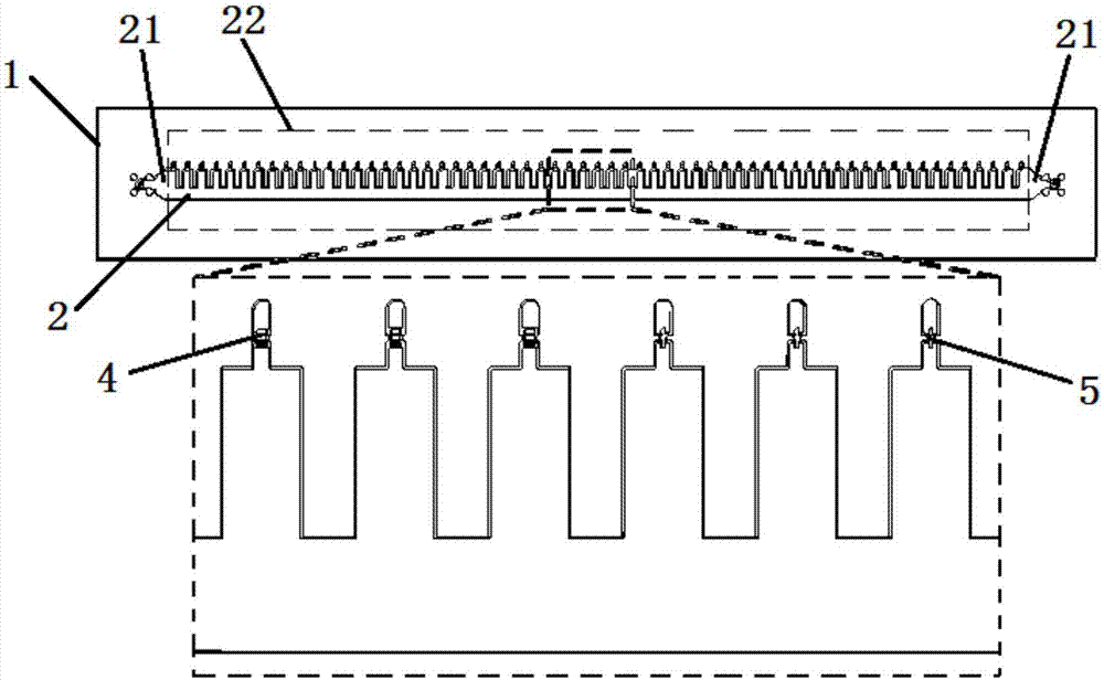
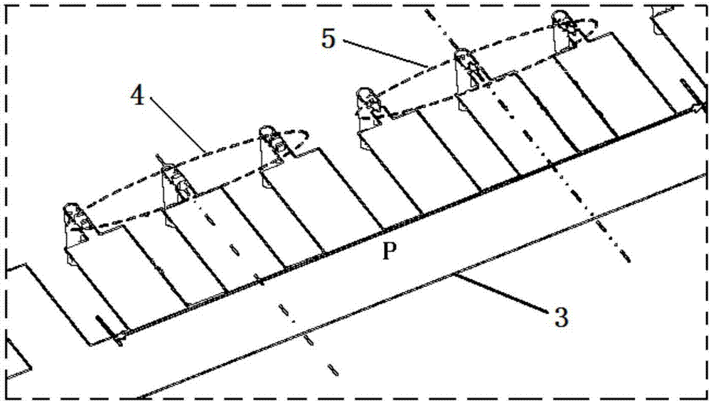
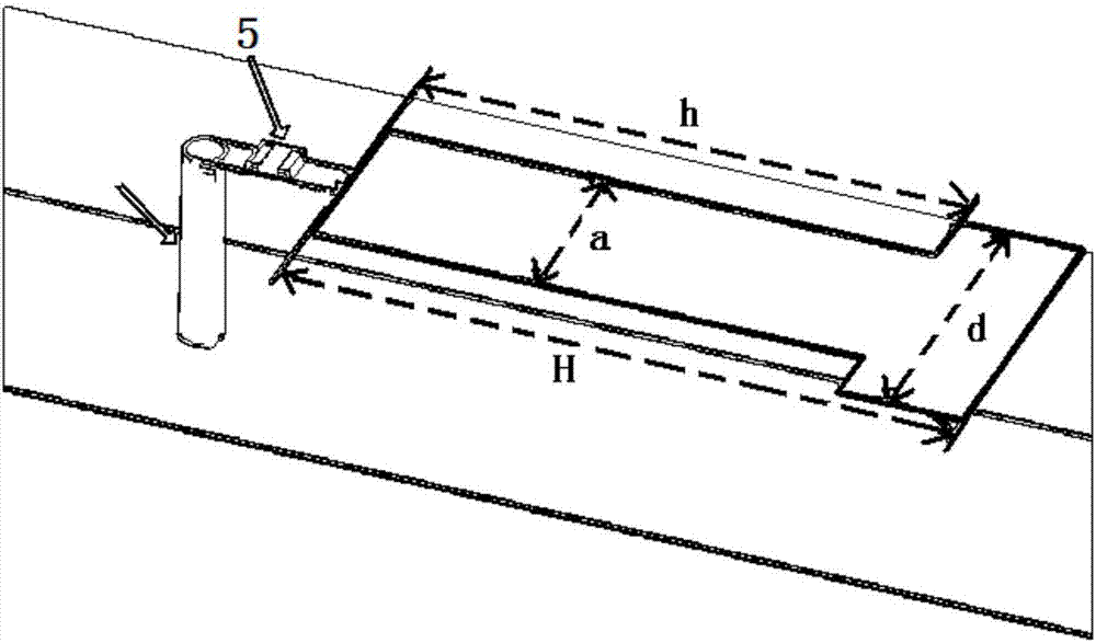
[0034] Such as figure 1 As shown, the transmission line and dual-band fixed-frequency beam scanning leaky-wave antenna multiplexing device of the present invention includes a dielectric substrate 1, a metal strip 2, a metal floor 3, some fixed capacitors 4 and some varactor diodes 5; the metal strip covers On the upper surface of the dielectric substrate, the metal floor covers the lower surface of the dielectric substrate, and the metal floor is used to make the leaky-wave antenna radiate to the upper half space. The material of the dielectric substrate is F4BK350, the thickness ts=3mm, and the overall length of the device is 332mm. A number of via holes are opened on the dielectric substrate, one end of the via hole is connected to the metal floor, the other end is connected to the fixed capacitor or variable capacitance diode, and the fi...


PUM


Abstract

The invention discloses a transmission line, a leaky-wave antenna multiplexing device and a beam scanning method thereof. The device comprises a dielectric substrate, a metal strip and a metal floorboard positioned on the front and back surfaces of the dielectric substrate, and periodically alternatively arranged capacitors and variable capacitance diodes for connecting the metal floorboard and the metal strip via the through holes. The metal strip comprises gradient microstrip line structures at two ends and an artificial surface plasmon structure positioned therebetween. When the capacitance value of the variable capacitance diode is identical with that of the fixed capacitor, the surface impedance of the device is identical, and thus the function of the transmission line is achieved; when the capacitance value of the variable capacitance diode is not identical with that of the fixed capacitor, the surface impedance of the device is periodically modulated, and thus the radiation function of the leaky-wave antenna is achieved. Voltage is used as a regulation means, and fixed frequency beam scanning can be achieved along with the change of the voltage; the device is simple to manufacture, convenient to operate and prone to integrate; only a photoetching step is needed, so that cost is saved, and machining errors caused by a multi-layer structure are avoided.

Description

technical field [0001] The invention relates to a microwave antenna, in particular to a transmission line and leaky wave antenna multiplexing device and a beam scanning method thereof. Background technique [0002] Surface plasmon is a surface electromagnetic wave mode, which is distributed at the interface between metal and medium, and tightly binds electromagnetic energy in a small area around the interface. It has sub-wavelength characteristics in the optical band and can be effectively transmitted. and localized light waves, which are widely used in optical communication systems. However, metals exhibit ideal electrical conductor properties in the microwave range, and cannot directly support surface plasmons at the interface between metal and dielectric. Therefore, an artificial surface plasmon based on a planar metal slot structure was proposed, whose dispersion characteristics are consistent with surface plasmon, which provides the possibility for designing planar pla...

Claims


Application Information

Patent Timeline
IPC IPC(8): H01Q1/38H01Q1/48H01Q13/20
CPCH01Q1/38H01Q1/48H01Q13/20H01Q13/206
Inventor 马慧锋王萌张浩驰魏楠崔铁军
Owner SOUTHEAST UNIV
Why Eureka
Try Eureka