
Vacuum dyeing machine

A dyeing machine and vacuum technology, applied in the field of vacuum dyeing machines, can solve the problems of fabric damage, affecting dye composition and color fineness, low efficiency, etc., and achieve the effect of preventing dye dosage and efficient dyeing

Active Publication Date: 2017-12-05
浙江深梦皮革科技有限公司
View PDF3 Cites 0 Cited by
  • Summary
  • Abstract
  • Description
  • Claims
  • Application Information

AI Technical Summary

Problems solved by technology

[0002] Traditional dyeing machines use exhaust dyeing and atomization dyeing, and the fabric needs to be dried after dyeing, which involves two roll-ups, the process is complicated and the efficiency is extremely low
[0003] The dyeing machine is suitable for linen, cotton, rayon, blended seamless underwear, stockings, silk, etc., through stirring and other methods, not only will the fabric be damaged, but also the sundries that fall off the fabric will affect the composition and fineness of the dye, which will affect the dyeing of the fabric. bad quality

Method used


Image

  • Vacuum dyeing machine
  • Vacuum dyeing machine
  • Vacuum dyeing machine

Examples


Embodiment Construction

[0030] The following are specific embodiments of the present invention and in conjunction with the accompanying drawings, the technical solutions of the present invention are further described, but the present invention is not limited to these embodiments.

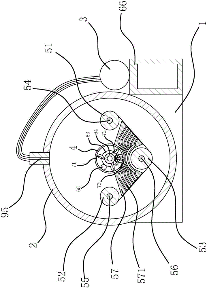
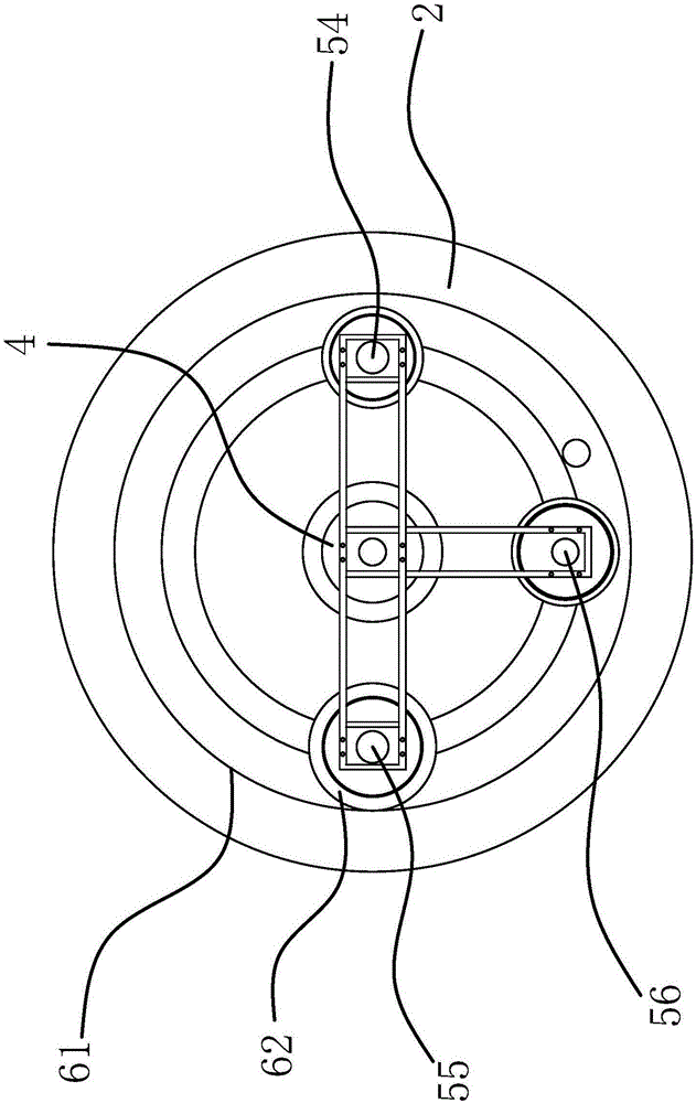
[0031] Such as figure 1 As shown, the dyeing machine includes a base 1, a barrel-shaped dyeing vat 2, a dye pool 66, a drip dyeing pump 3 and a main shaft 4. The dyeing vat 2 is fixed on the base 1, the main shaft 4 is a hollow structure, and the main shaft 4 is connected to a motor. The dyeing vat 2 is rotatably connected with a discharge drum 51, a receiving drum 52 and a tensioning drum 53, and the discharging drum 51, the receiving drum 52 and the tensioning drum 53 are connected to the dyeing vat through the first rotating shaft 54, the second rotating shaft 55 and the third rotating shaft 56 respectively. 2 are connected, rotating shaft 1 54, rotating shaft 2 55 and rotating shaft 3 56 are all fixedly connected with ...


PUM


Abstract

The invention provides a vacuum dyeing machine and belongs to the textile technology field. The technical problems that an existing dyeing machine is complex in process and drying cannot be conducted are solved. The vacuum dyeing machine comprises a base, a cylindrical dyeing vat, a dye pool, a droplet dyeing pump and a main shaft. The dyeing vat is arranged on the base, the main shaft is of a hollow structure, the dyeing vat is rotationally connected with a material discharging drum, a material receiving drum and a tension drum, the material discharging drum, the material receiving drum and the tension drum are connected with the dyeing vat through a first rotary shaft, a second rotary shaft and a third rotary shaft respectively, and the first rotary shaft, the second rotary shaft and the third rotary shaft are fixedly connected with the main shaft. A material suction block is arranged between the material discharging drum and the material receiving drum, material suction holes for to-be-dyed cloth are formed in the material suction block, a vacuum pumping device for vacuumizing the dyeing vat is arranged on the main shaft, and a drive structure driven by the main shaft to drive the material receiving drum to rotate is arranged between the dyeing vat and the material receiving drum. The vacuum dyeing machine has the advantages that the cloth can be dried while dyed.

Description

technical field [0001] The invention belongs to the technical field of textiles and relates to a vacuum dyeing machine. Background technique [0002] Traditional dyeing machines adopt exhaust dyeing and atomization dyeing methods, and the fabric needs to be dried after dyeing, which involves two windings, the process is complicated and the efficiency is extremely low. [0003] The dyeing machine is suitable for hemp, cotton, rayon, blended seamless underwear, stockings, silk, etc. By stirring and other methods, not only the fabric will be damaged, but also the sundries that fall off the fabric will affect the composition and fineness of the dye, which will affect the dyeing of the fabric. Bad quality. Contents of the invention [0004] The purpose of the present invention is to provide a vacuum dyeing machine aiming at the above-mentioned problems existing in the existing technology. The technical problem to be solved by the present invention is how to continuously circul...

Claims


Application Information

Patent Timeline
Patent Type & Authority Applications(China)
IPC IPC(8): D06B5/08D06B23/20D06B23/04D06B15/09D06B23/00
CPCD06B23/04D06B23/20D06B3/16D06B3/203D06B3/34D06B15/04D06B2700/36
Inventor 徐寿春丁友新龚道进
Owner 浙江深梦皮革科技有限公司
Learn More