Sliding component and method

A technology of sliding parts and particles, applied in the direction of anti-centrifugal rotating parts, engine components, chemical instruments and methods, etc.

Inactive Publication Date: 2017-12-12
MAHLE INT GMBH +1
View PDF2 Cites 0 Cited by
  • Summary
  • Abstract
  • Description
  • Claims
  • Application Information

AI Technical Summary

Problems solved by technology

However, the incorporation of hard particles and the use of pulsed or alternating deposition potentials prevent the formation of columnar grain structures, making the tin matrix a dull tin layer rather than a more robust bright tin layer

Method used


Image

  • Sliding component and method
  • Sliding component and method
  • Sliding component and method

Examples


Embodiment Construction

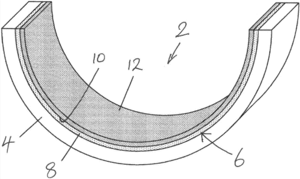
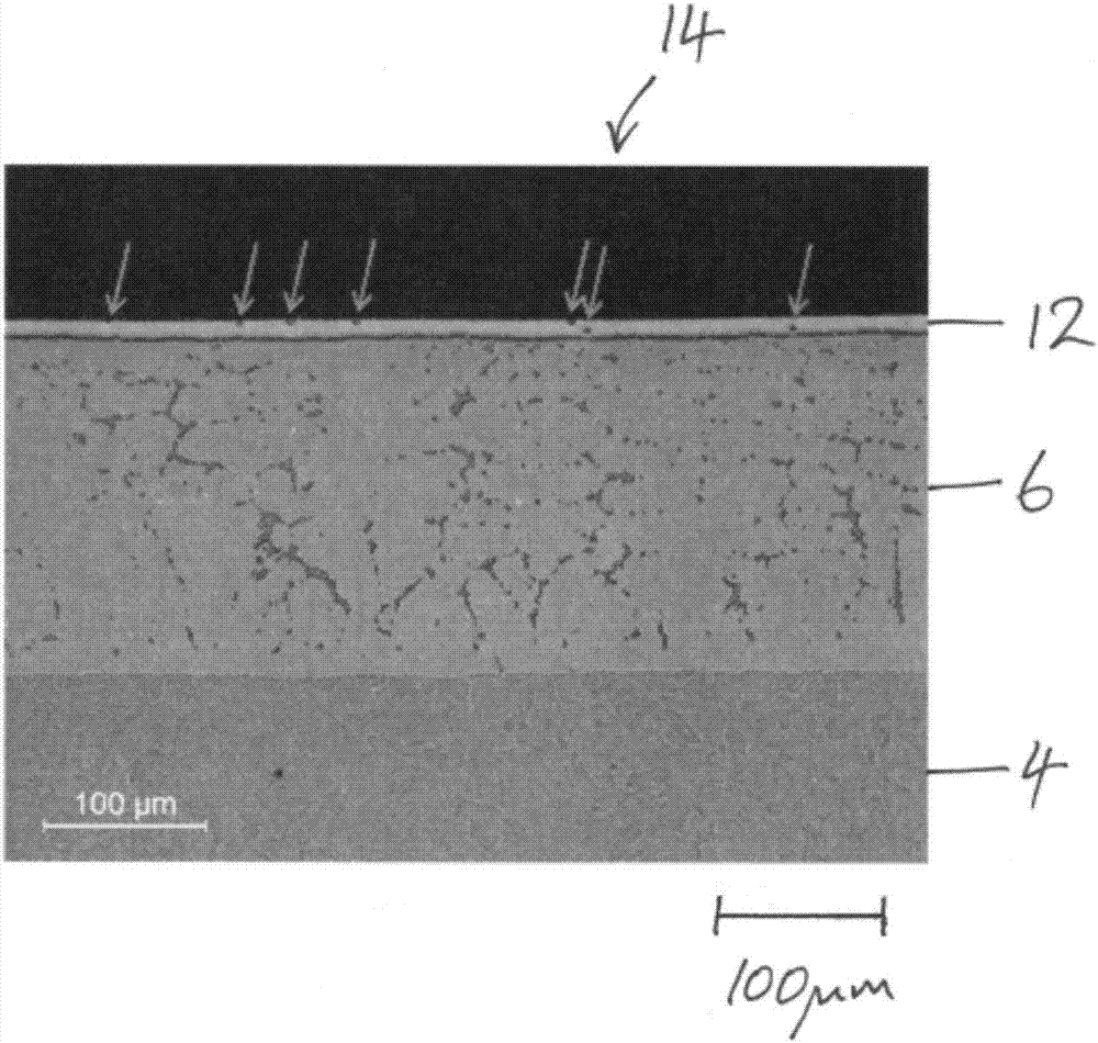
[0035] figure 1 Shown is a half-bearing, or half-cylindrical bearing shell 2 , of a main bearing assembly of an internal combustion engine for holding a cylindrical journal of a crankshaft. The bearing half includes a half-cylindrical bearing shell. The bearing shell has a layered structure incorporating a steel backing 4 . The backing is coated or bonded to a liner layer 6 comprising a copper-tin bronze and nickel diffused film, or layer 8 of the intermediate layer 10 . The coating 12 is formed by electroplating on the intermediate layer.

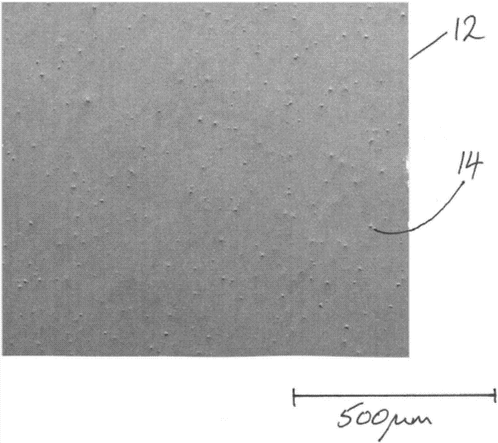
[0036] Coatings include Ni in a tin matrix 3 particles of Al, the tin matrix is ​​formed by electroplating on the intermediate layer. The intermediate layer is arranged as a cathode in a bath containing a plating electrolyte and an anode, and a cathode bias (ie, a negative bias) is applied to the cathode relative to the anode. The cathode bias drives the positively charged metal ions, such as tin, towards the cathode and deposits the ...


PUM

PropertyMeasurementUnit
thicknessaaaaaaaaaa
sizeaaaaaaaaaa
interface potentialaaaaaaaaaa

Abstract

An overlay of a sliding component, such as a sliding component for an engine, may provide a bearing surface against a steel journal, for example. The overlay may include intermetallic particles disposed in a matrix including tin (Sn). The matrix may be formed by electroplating. Examples of intermetallic particles include, but are not limited to, aluminides and nickel aluminides. The matrix may include an electroplated matrix of tin and/or a tin alloy.

Description

technical field [0001] The invention relates to a sliding part and a method for producing a sliding part. In particular, the invention relates to a coating of a sliding part and a method for producing said coating. The sliding part may be a sliding part for an engine, such as a bearing, a bearing housing, a bush, a thrust washer, a journal bearing or the like. Background technique [0002] In internal combustion engines, each main bearing assembly typically includes a pair of half bearings that hold the cylindrical journals of the crankshaft. Each half-bearing includes a semi-cylindrical bearing shell. Bearing shells typically have a layered structure to provide the desired mechanical properties. The strong backing material provides structural strength and is coated with one or more layers having preferred tribological properties to provide bearing surfaces facing and supporting the cooperating crankshaft journals. The backing is typically steel, 1 mm or more thick, and ...

Claims


Application Information

Patent Timeline
Patent Type & Authority Applications(China)
IPC IPC(8): C25D3/30C25D15/00F16C33/06
CPCC25D7/10F16C33/12C25D3/30C25D15/00F16C33/06B22D15/02B22D19/08F16C9/02F16C33/121F16C33/124F16C33/208F16C2204/12F16C2223/32F16C2223/42F16C2223/70F16C2240/60F16C2360/22B32B15/01C23C4/08
Inventor 约翰·卡赖伊萨克·章罗杰·戈杰斯伊恩·莱恩戴维·莱瑟姆
Owner MAHLE INT GMBH
Why Eureka
Try Eureka