Waste gas collecting device

A collection device and exhaust gas technology, applied in the direction of measuring device, sampling device, sampling, etc., can solve the problems of uneven sampling, high replacement frequency, low sensitivity, etc., and achieve the effect of being suitable for popularization, accurate detection results, economical and practical

Pending Publication Date: 2017-12-15
南京圆点环境清洁技术有限公司
View PDF0 Cites 2 Cited by
  • Summary
  • Abstract
  • Description
  • Claims
  • Application Information

AI Technical Summary

Problems solved by technology

The collection of waste gas is very important. The collection of waste gas in the prior art mainly has the following problems: 1. In the prior art, a sampling port is set on the pipeline, and a collector (such as a sampling tube) is set on the sampling port, which is used for detection after direct sampling. The sampling is not uniform, and the detection results of organic gases in the waste gas are biased; the test results cannot accurately display the residual amount of organic gases in the waste gas; 2. The temperature of the waste gas is relatively high, generally at 200-400 ° C, and the organic gas has Certain corrosiveness, ordinary sampling tubes are seriously damaged, and the frequency of replacement is high; due to the need to stop business during replacement, it seriously affects the working effect of exhaust gas treatment; at the same time, due to the high temperature of exhaust gas, personnel are easy to burn when sampling; 3. Sampling tube sampling When the final exhaust gas is detected by a high-efficiency gas phase detector, due to the low content of volatile organic gases in the exhaust gas, direct detection has low sensitivity, the detection result is not significant, the detection effect is not good, and the detection result is inaccurate

Method used


Image

  • Waste gas collecting device
  • Waste gas collecting device
  • Waste gas collecting device

Examples


Embodiment 1

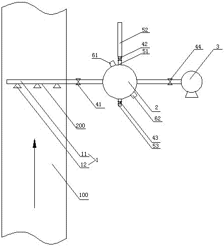
[0028] like figure 1 As shown, an exhaust gas collection device 100 is arranged on an exhaust gas discharge pipe 200 . Arrows in the figure indicate the flow direction of exhaust gas. The exhaust gas collection device includes a sampling pipe 1 , a sampler 2 connected to the sampling pipe, and an air pump 3 connected to the sampler.

[0029] The sampling pipe includes a main pipe 11, and several branch pipes 12 are arranged on one side of the main pipe. type, the activated carbon adsorption layer is filled in the sample loader; the upper side of the sample loader is provided with a liquid inlet 51, which is connected to a liquid inlet pipe 52, and a second valve 42 is arranged between the liquid inlet and the liquid inlet pipe. The lower side of the device is provided with a drain port 53, and the drain port is provided with a third valve 43.

[0030] As an improvement of the present invention, an activated carbon inlet 61 is provided on the upper side of the sample loader,...

Embodiment 2

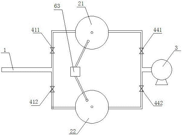
[0037] like figure 2 As shown, an exhaust gas collection device 100, the sampling tube of the exhaust gas collection device is connected to two sample loaders in parallel, the sample loader includes a sample loader A21 and a sample loader B22, and a second A valve A411, a fourth valve A441 is set between the sample loader A and the air pump, a first valve B412 is set between the sample loader B and the sampling tube, and a fourth valve B442 is set between the sample loader B and the air pump. All the other structures are consistent with Example 1.

Embodiment 3

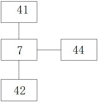
[0039] like image 3 As shown, the exhaust gas collection devices shown in Embodiment 1 and Embodiment 2 are equipped with a controller 7, the controller is electrically connected to the first valve, the second valve, and the fourth valve, and the controller can control the opening and closing of each valve. , can set the opening and closing time of each valve, opening and closing sequence, to achieve accurate operation and reduce errors.


PUM


Abstract

The invention discloses a waste gas collection device, which comprises a sampling pipe, a sampler connected to the sampling pipe, and an air pump connected to the sampler. There is a first valve between the tube and the sample loader; the sample loader is spherical, and the activated carbon adsorption layer is filled in the sample loader; the sample loader is provided with a liquid inlet and a liquid discharge port, and the liquid inlet is connected to the liquid inlet pipe. A second valve is arranged between the liquid inlet and the liquid inlet pipe, and a third valve is arranged at the liquid outlet. The advantages of the present invention are: adopting the waste gas collection device to collect waste gas can uniformly collect waste gas, and at the same time make the detection result more accurate and the detection effect good; the present invention is easy to use, simple to operate, suitable for popularization and use, and economical and practical.

Description

technical field [0001] The invention relates to the technical field of waste gas treatment, in particular to a waste gas collection device. Background technique [0002] Industrial waste gas refers to the general term for all kinds of pollutant gases that are discharged into the air during fuel combustion and production processes in the enterprise factory area. Common industrial waste gases mainly include carbon dioxide, carbon disulfide, hydrogen sulfide, fluoride, nitrogen oxides, chlorine, hydrogen chloride, carbon monoxide, sulfuric acid (fog), lead mercury, beryllium compounds, smoke and productive dust. It also includes some volatile volatile organic gases, such as benzene, toluene, xylene, ethyl acetate, acetone butanone, ethanol, acrylic acid, formaldehyde and other volatile organic gases, especially volatile organic gases in chemical plants. The content of industrial waste gas is relatively high, and the direct discharge of volatile volatile organic gases not only ...

Claims


Application Information

Patent Timeline
Patent Type & Authority Applications(China)
IPC IPC(8): G01N1/22G01N1/40
CPCG01N1/2214G01N1/2247
Inventor 胡家富杨瑞成朱麟
Owner 南京圆点环境清洁技术有限公司
Why Eureka
Try Eureka