
Testing method and device for influence relation of thermal contact resistance of bonding surface by normal load

A technology of contact thermal resistance and measuring device, which is applied in the direction of material thermal development, etc., can solve the problems of unsuitable equipment and affect the contact thermal resistance of the contact surface, etc., and achieve the effect of convenient production.

Inactive Publication Date: 2017-12-19
BEIJING UNIV OF TECH
View PDF9 Cites 6 Cited by
  • Summary
  • Abstract
  • Description
  • Claims
  • Application Information

AI Technical Summary

Problems solved by technology

However, in summary, it can be found that whether it is the contact thermal resistance of the simple joint surface between the long axis or the cuboid, or the contact thermal resistance of the interface between the cylindrical sleeve walls and the research on the experimental device, it is only carried out in a steady state. The equipment in the actual processing process is not applicable, and the actual processing operation will be subjected to different loads, which will affect the contact thermal resistance of the contact surface

Method used


Image

  • Testing method and device for influence relation of thermal contact resistance of bonding surface by normal load
  • Testing method and device for influence relation of thermal contact resistance of bonding surface by normal load
  • Testing method and device for influence relation of thermal contact resistance of bonding surface by normal load

Examples


Embodiment 1

[0020] The first step, preparation of test specimens and equipment

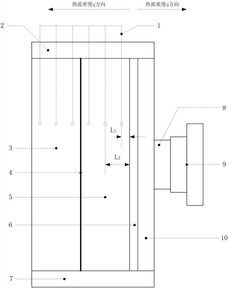
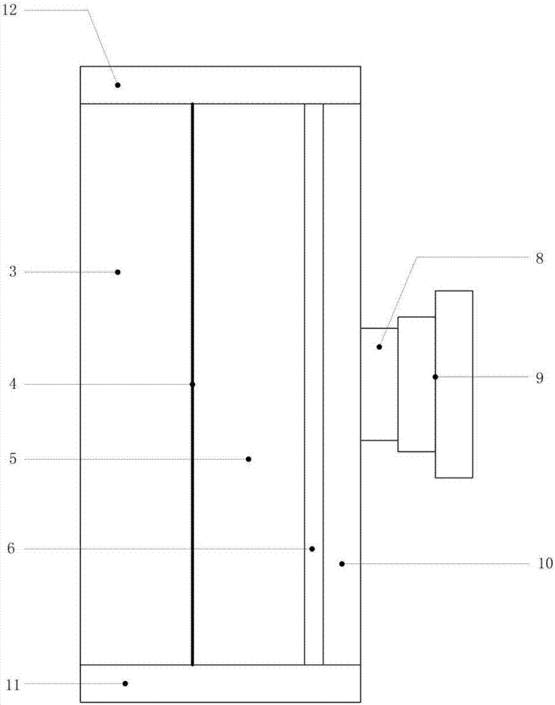
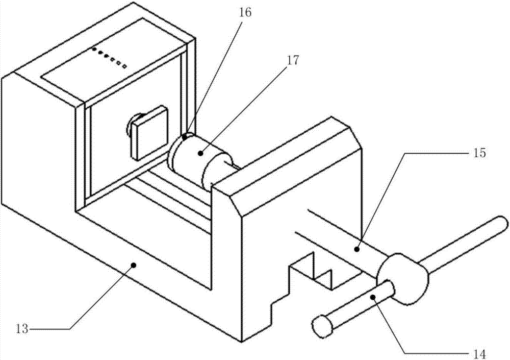
[0021] Take two pieces to be tested (specification 150×130×30), that is, the outer test piece 3 and the inner test piece 5, and place them side by side; in addition, place the heating device 6 (specification 150×130×4) closely with the inner test piece 5 Bonding; then the sensor fixing device 10 (specification 150 × 130 × 10) is closely attached to the other side of the heating device 6, the sensor fixing device 10 has the function of fixing the pressure sensor 8, and also has the function of making the heating device 6 The effect of the heat generated is evenly transmitted from left to right; the sensor block 9 is installed on the pressure sensor 8, its purpose is to protect the pressure sensor 8, in addition to making the applied force more uniform on the sensor; in the device The upper, lower, front and rear are respectively provided with upper heat insulation device 2 (specification 170×74×10), lower heat...

Embodiment 2

[0038] The difference from Example 1 is that the two test pieces are made of different materials from the first two test pieces in the embodiment, and the other conditions are kept the same. Through the above steps, the contact thermal resistance and normal direction of the joint surface of the two test pieces of different materials are obtained. load relationship.

Embodiment 3

[0040] The difference from Example 1 is that the surface roughness value Ra of the two test pieces is changed, and other conditions remain unchanged. Through the above steps, the contact heat of the joint surface of the two test pieces is obtained under different surface roughness Ra conditions. The relationship between resistance and normal load.


PUM


Abstract

The invention discloses a testing method and device for an influence relation of thermal contact resistance of a bonding surface by a normal load and belongs to the technical field of thermal conduction and thermal-mechanical coupling tests of solid-state materials. According to the testing method, two rectangular testing parts and one rectangular heating plate are used for creating a one-dimensional stable heat-conducting environment which is used for conducting along the rectangular testing parts and along the X direction. The load, which is borne by load simulation equipment in an operation process, is applied to the other side of the heating plate. Temperature measurement sensors, which are uniformly distributed on the rectangular testing parts, are used for measuring temperature of different radiuses in the X direction; meanwhile, heat insulation devices are arranged at the upper, lower, front and back parts of the testing device, and the measurement of the thermal contact resistance of a bonding surface to be tested in an actual operation process is realized according to transmission distribution of a temperature gradient along the X direction and hot flow density. By adopting the testing method and device, disclosed by the invention, the disadvantages of tests on the thermal contact resistance of the bonding surface in the prior art are overcome; a measurement device is convenient to manufacture and a measured result meets experiment requirements; the testing method and device can be used for the fields including engineering practice, teaching, scientific researches and the like.

Description

technical field [0001] The invention relates to a method and a device for measuring the influence relationship of a normal load on a joint surface contact thermal resistance, and belongs to the technical field of solid material heat conduction and thermomechanical coupling tests. Background technique [0002] The matching relationship of parts in the machinery industry is very important. The surfaces that contact each other between parts are joint surfaces. Usually, when two solid materials are in contact with each other, it is often considered that the two contacting surfaces are in complete contact. But in fact this is not the case, because the surface of each part is not absolutely smooth, there are large and small bumps and pits on the surface, so that the two surfaces cannot be completely contacted. Moreover, when one of the components is heated by external force, the heat will be transferred from the high-temperature object to the low-temperature object. During the hea...

Claims


Application Information

Patent Timeline
Patent Type & Authority Applications(China)
IPC IPC(8): G01N25/20
CPCG01N25/20
Inventor 王建华张再尚刘志峰李迎
Owner BEIJING UNIV OF TECH
Learn More