An ultra-high-speed shutter semiconductor image sensor
An image sensor and semiconductor technology, applied in semiconductor devices, electric solid state devices, radiation control devices, etc., can solve the problem of difficulty in the sensor layer, and achieve the effects of improving time resolution, simplifying design, and improving resolution.
- Summary
- Abstract
- Description
- Claims
- Application Information
AI Technical Summary
Problems solved by technology
Method used
Image
Examples
Embodiment 1
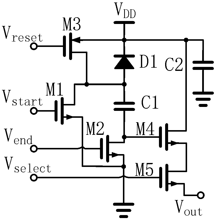
[0029] figure 1 It is an equivalent schematic diagram of the pixel unit circuit in this embodiment, wherein the photodiode D1 uses a p+ / n well photodiode, the side length of the p+ region is 7 microns, and the pixel pitch is 24 microns. Capacitor C1 is a signal storage capacitor, which is implemented using polysilicon-polysilicon capacitors. Capacitor C2 is a power supply decoupling capacitor, which uses a polysilicon gate-n+ capacitor, that is, a depletion-type NMOS transistor capacitor. M1 and M2 are respectively an exposure start control transistor and an exposure end control transistor, M3 is a reset transistor, and M4 and M5 form a readout buffer and selection circuit.
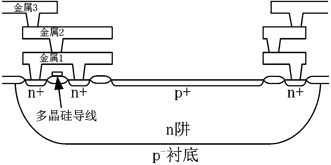
[0030] In this embodiment, the cross section of photodiode D1 is as follows figure 2shown. In order to fully shield stray light, especially for the drain of M2, except for an opening at the position of photodiode D1, other positions are covered by a light-shielding layer made of top metal. The edge o...
Embodiment 2
[0037] Example 1: The ultra-high shutter speed global shutter semiconductor image sensor realized by standard CMOS mixed-signal technology has excellent shutter efficiency only for short-wavelength visible light and ultraviolet light, but the residual sensitivity to 650nm red light is as high as 14,000 points one.
[0038] However, the ultra-high shutter speed global shutter semiconductor image sensor of this embodiment uses a triple-well CMOS mixed-signal process, and is realized by a deep n-well CMOS mixed-signal process including an isolated p-well. Among them, in figure 1 The equivalent schematic diagram of the pixel unit circuit shown, the exposure end control body port p-well of NMOS transistor M2 is a grounded isolated p-well in a deep n-well connected to a high potential, below which is a grounded p-well type substrate. The purpose of shielding the bulk port p-well of M2 with deep n-well isolation is to shield stray photogenerated carriers, thereby further improving ...
Embodiment 3
[0040] In Example 2, if the substrate-isolated p-well of the exposure end control transistor M2 is connected to a potential lower than the ground instead of the ground and the corresponding power supply decoupling capacitance is increased, although the dark current signal can also be reduced, the dark current is reduced to a limited extent and also has an impact on imaging sensor performance. At the same time, the power supply decoupling capacitor will occupy a large amount of chip area.
[0041] Figure 5 It is an equivalent schematic diagram of the pixel unit circuit in the third embodiment. The source of M2 is connected to the output of the CMOS inverter composed of transistors M6, M7, rather than directly connected to ground. M7 is an NMOS transistor with the shortest gate length and large gate width. When a few nanoseconds or more have elapsed since the exposure ends, V reset Turning to low level, the output terminal of the inverter composed of M6 and M7, that is, the...
PUM
 Abstract
Description
Claims
Application Information
 - R&D
- Intellectual Property
- Life Sciences
- Materials
- Tech Scout
- Unparalleled Data Quality
- Higher Quality Content
- 60% Fewer Hallucinations
Browse by: Latest US Patents, China's latest patents, Technical Efficacy Thesaurus, Application Domain, Technology Topic, Popular Technical Reports.
© 2025 PatSnap. All rights reserved.Legal|Privacy policy|Modern Slavery Act Transparency Statement|Sitemap|About US| Contact US: help@patsnap.com


