Double-station bent arm connecting rod motor structure

A double-station, electric motor technology, applied in other household appliances, household appliances, applications, etc., can solve the problems of low output efficiency of blow molding, time loss of invalid waiting, and inability to realize double-station cycle blow molding, etc., to achieve Compact structure, fast mold clamping and space-saving effect

Pending Publication Date: 2017-12-22
开平雅琪塑胶机械模具厂
View PDF5 Cites 0 Cited by
  • Summary
  • Abstract
  • Description
  • Claims
  • Application Information

AI Technical Summary

Problems solved by technology

Most of the blow molding machines in the prior art have a single-station structure, that is, a single station; usually a die head corresponds to a mold clamping mechanism, and its operation process is that after the tube blank is extruded from the die head, it undergoes mold clamping, air blowing, etc. , cooling molding, mold opening and blanking, etc., during the above molding process from mold closing to blanking, the die head will stop feeding and extruding. At this time, the blow molding machine has the ability to continuously supply materials, but it must not Do not wait for the completion of the above-mentioned mold closing to blanking process, resulting in waste of time spent waiting, and low blow molding output efficiency; and because the existing structure of the die head is a fixed structure, the effect of double-station cycle blow molding cannot be achieved , it is necessary to stop the extruder from feeding

Method used


Image

  • Double-station bent arm connecting rod motor structure
  • Double-station bent arm connecting rod motor structure
  • Double-station bent arm connecting rod motor structure

Examples


Embodiment 1

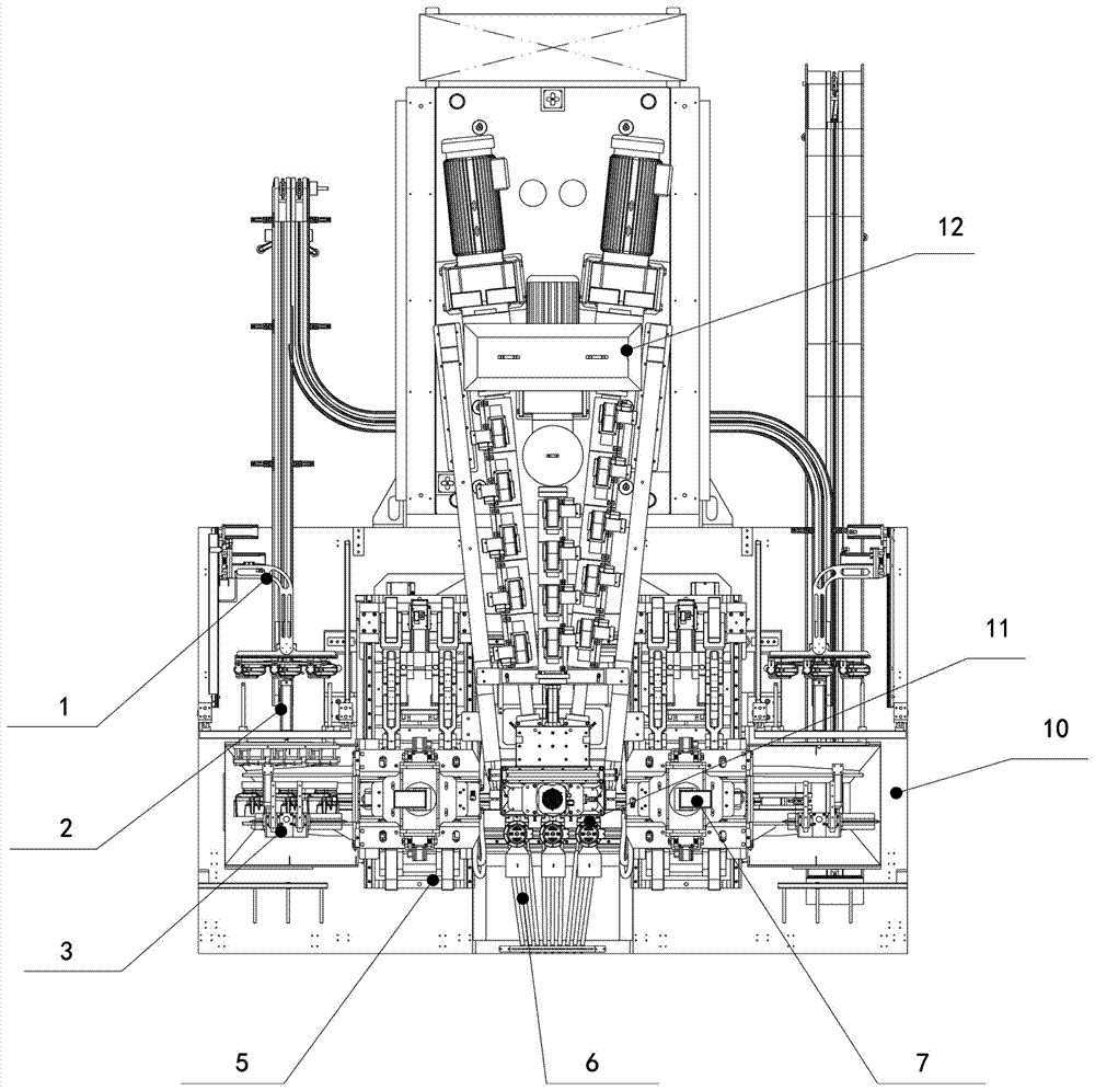
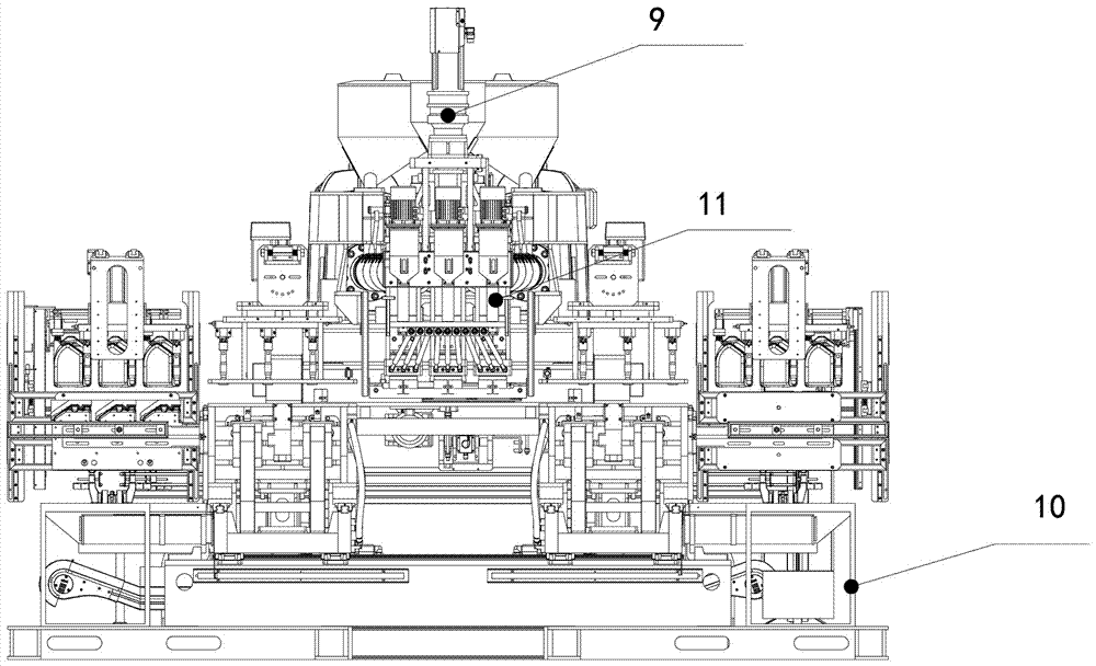
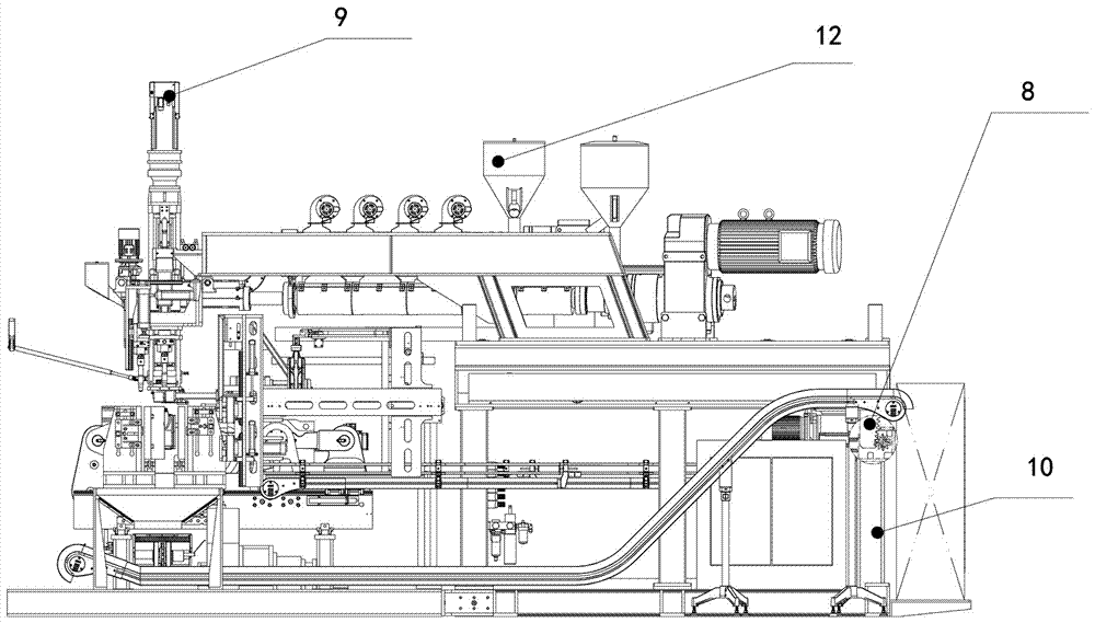
[0040] The structure of a double-station crank arm connecting rod motor described in Embodiment 1, such as figure 1 , figure 2 , image 3 and Figure 4 As shown, it includes a frame workbench 10, an extruder 12 with an extruder head 11 is arranged on the frame workbench, and a blow molding mechanism with double stations and the same structure is arranged symmetrically on the left and right sides of the extruder; The blow molding mechanism includes a mold clamping device 5 that can move in and out of the center of the extruder head to realize mold clamping, mold removal and film change, and also includes a mold clamping device that can blow the liquid glue after injecting the mold and moving the mold. Air-forming blowing seat device 7. The secondary sizing device installed on the blowing seat device for secondary sizing of the formed product by cold air 3. Set on the workbench of the machine frame to sizing the formed product after the secondary sizing of the cold air Mater...


PUM


Abstract

The invention discloses a double-station bent arm connecting rod motor structure comprising a rack workbench, an extruder with an extruder head, and a blow molding mechanism forming a double-station same structure. The blow molding mechanism comprises a mold locking device, and the mold locking device can move into and move out of the lower portion of the center of the extruder head and achieves mold locking, mold moving and mold changing. The blow molding mechanism further comprises a blowing seat device, a secondary sizing device, an excess material removal device and a manipulator device. The blowing seat device conducts blowing forming on liquid glue after glue injection and mold moving of the mold locking device. The manipulator device is arranged on the rack workbench and takes a finished product after excess material removal of the finished product. The extruder is further provided with a pre-sealing transverse cutting knife device which conducts synchronous actions of pre-sealing / opening and transverse cutting-off of flowing glue of the extruder head after glue injection and mold locking through the mold locking device. The extruder is provided with a glue pull device and is connected with an adjusting mouth mold device adjusting the position and angle of a glue flowing opening of the extruder head. The rack workbench is further provided with a rack head lifting device which is connected with the extruder and achieves lifting of the extruder head of the extruder.

Description

technical field [0001] The present invention relates to the field of blow molding machinery, in particular to a method for realizing double-station work by lifting the extruder head up and down and the mold clamping device using a curved arm connecting rod structure, etc. It is a double-station crank arm connecting rod motor structure production equipment for cycle production of blow molding. Background technique [0002] Blow molding machine, also known as hollow blow molding machine, is a rapidly developing plastic processing equipment. The blow molding machine is to spray out the liquid plastic, and use the wind blown out by the machine to blow the plastic body to a mold cavity of a certain shape to make a product. Most of the blow molding machines in the prior art have a single-station structure, that is, a single station; usually a die head corresponds to a mold clamping mechanism. , cooling molding, mold opening and blanking, etc. During the molding process from mold...

Claims


Application Information

Patent Timeline
Patent Type & Authority Applications(China)
IPC IPC(8): B29C49/04B29C49/42B29C49/70B29C49/78B29C49/56B29L22/00
CPCB29C49/04B29C49/42B29C49/4205B29C49/70B29C49/78B29C2049/566B29L2022/00B29C49/04106
Inventor 谭炳立
Owner 开平雅琪塑胶机械模具厂
Why Eureka
Try Eureka