Low-temperature air cooling screw heat pump system

An air-cooled screw and heat pump system technology, applied in refrigerators, refrigeration components, refrigeration and liquefaction, etc., can solve the problems affecting the smoothness of the compressor, start-up under load, etc., to prevent the phenomenon of start-up under load, reduce influence, condensation low temperature effect

Inactive Publication Date: 2017-12-26
WUXI VOCATIONAL & TECHN COLLEGE
View PDF8 Cites 7 Cited by
  • Summary
  • Abstract
  • Description
  • Claims
  • Application Information

AI Technical Summary

Problems solved by technology

If the screw compressors are directly connected in parallel, there may be a ph...

Method used


Image

  • Low-temperature air cooling screw heat pump system
  • Low-temperature air cooling screw heat pump system
  • Low-temperature air cooling screw heat pump system

Examples


Embodiment 1

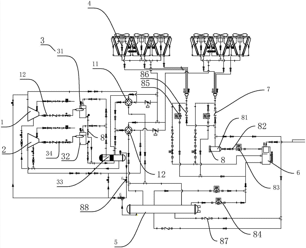
[0063] Embodiment 1, a low-temperature air-cooled screw heat pump system, the main components of the cycle include: two screw compressors, three oil separators, two four-way reversing valves, one flash economizer 6, one Typhoon cold fin tube heat exchanger, one shell and tube heat exchanger 5, two cooling expansion valves 84, two heating expansion valves 85 and one main liquid supply electronic expansion valve 83. Such as figure 1 As shown, the first screw compressor 1 and the second screw compressor 2 are arranged in parallel, and the first screw compressor 1 and the second screw compressor 2 are equipped with a muffler 12 to reduce the noise during operation. The air inlets of the two compressors are provided with one-way exhaust valves communicating with them to control the flow of air.

[0064] Such as figure 1 As shown, an oil separation unit 3 is provided outside the two screw compressors, and the oil separation unit 3 includes a secondary oil separator 33 . The first...

Embodiment 2

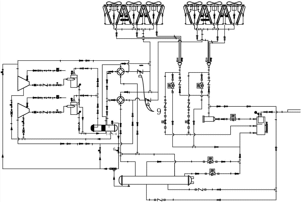
[0073] Embodiment 2, a kind of low-temperature air-cooled screw heat pump system, such as figure 2 As shown, the first four-way reversing valve 11 is connected to the air return port of the air-cooled finned tube heat exchanger, and the suction butterfly valve 9 is installed on the pipeline, while the second four-way reversing valve 21 is connected to another set of air-cooled finned tubes. The air return port of the tube heat exchanger assembly is connected, and a suction butterfly valve 9 is also installed on the pipeline.

Embodiment 3

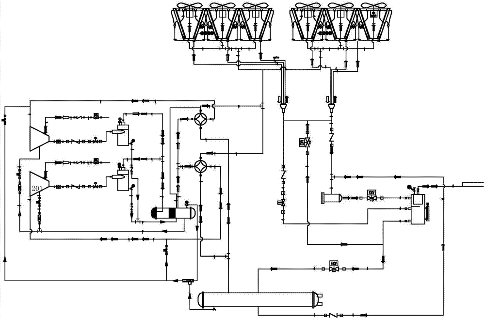
[0074] Embodiment 3, a kind of low-temperature air-cooled screw heat pump system, such as image 3 As shown, the difference from Embodiment 1 or 2 is that the refrigeration expansion valve 84 and the heating expansion valve 85 are shared, and the refrigeration one-way valve 86 and the heating one-way valve 87 are two-way design, that is, the front of the valve is connected in parallel, After the valve is connected in parallel. According to design requirements, a large-capacity refrigeration system can use two-way parallel small valves or a single large valve, and a small-capacity system can use a single small valve.


PUM


Abstract

The invention discloses a low-temperature air cooling screw heat pump system, and aims at providing a low-temperature air cooling screw heat pump system which has the beneficial effects that the operating efficiency and refrigeration performance of the system can be improved and the phenomenon of compressor loaded starting cannot be generated. According to the technical scheme, the low-temperature air cooling screw heat pump system is characterized in that a first screw compressor and a second screw compressor communicate with air cooling fin type heat exchangers through a first four-way reversing valve and a second four-way reversing valve correspondingly; the first four-way reversing valve and the second four-way reversing valve further communicate into a pipe type heat exchanger; the air cooling fin type heat exchangers further communicate with a flash type economizer; a refrigeration one-way valve is arranged between each air cooling fin type heat exchanger and the flash type economizer; the first screw compressor and the second screw compressor are each provided with an independent air suction pipeline, an independent exhaust pipe and an independent compressor oil return pipeline, it can be guaranteed that loops of the two compressors independently run and are independently started, mutual influence is avoided, and a reliable lubricating oil pipeline is guaranteed; and the efficiency under part of loads is increased, and the cost is reduced.

Description

technical field [0001] The invention relates to the field of refrigeration and air-conditioning equipment, in particular to a low-temperature air-cooled screw heat pump system. Background technique [0002] The air-cooled heat pump unit is a circulation system composed of compressors, heat exchangers, throttles, heat absorbers and other devices. The refrigerant circulates in the system under the action of the compressor. The refrigerant completes the process of increasing the pressure and temperature of the gaseous state in the compressor, and exchanges heat with the wind after entering the heat exchanger, and is cooled and converted into a liquid state. [0003] When the refrigerant runs to the heat absorber, the liquid state quickly absorbs heat and evaporates and turns into a gaseous state again. At this time, the air around the heat absorber will continuously transfer low-temperature heat to the refrigerant. The continuous circulation of the refrigerant realizes the pr...

Claims


Application Information

Patent Timeline
IPC IPC(8): F25B13/00F25B41/00F25B41/04F25B43/02F25B41/06F25B41/20F25B41/31
CPCF25B13/00F25B43/02F25B2313/02742F25B41/40F25B41/20F25B41/31
Inventor 商萍君任重威
Owner WUXI VOCATIONAL & TECHN COLLEGE
Why Eureka
Try Eureka