Device and method for coupling straw degradation and biogas slurry filtering

A coupling device and lifting device technology, which is applied in the field of straw degradation and biogas slurry filtration coupling device, can solve the problems of waste of agricultural and forestry waste resources, environmental pollution, etc., and achieve the effect of reducing manpower and material resources and facilitating loading and unloading

Inactive Publication Date: 2018-01-05
NORTHWEST A & F UNIV
View PDF0 Cites 2 Cited by
  • Summary
  • Abstract
  • Description
  • Claims
  • Application Information

AI Technical Summary

Problems solved by technology

If the straw raw material is not pretreated and used directly for fermentation and composting, the lignocellulose in the straw is difficult to be degraded by microorgani

Method used


Image

  • Device and method for coupling straw degradation and biogas slurry filtering

Examples


Embodiment 1

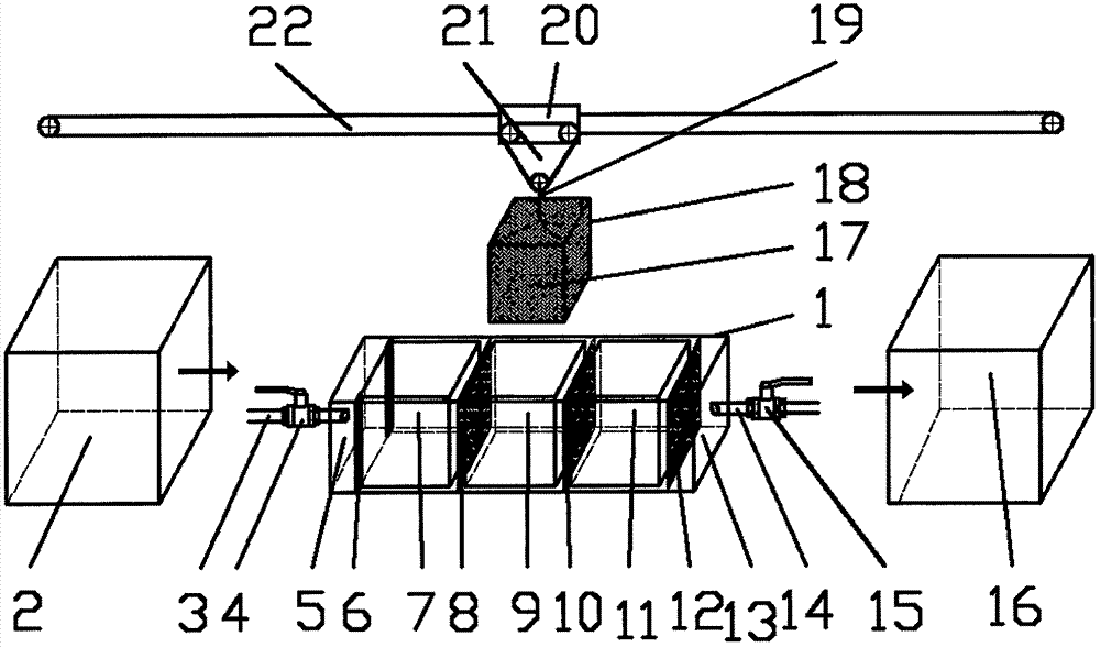
[0024] A straw degradation and biogas slurry filtration coupling device and method include a straw pre-treatment chamber 2, a biogas slurry filter tank housing 1, a horizontal moving lifting device, and a straw post-treatment chamber 16;

[0025] The left end of the biogas slurry filter housing 1 is provided with a biogas slurry raw liquid input pipe 3, and the right end is provided with a biogas slurry filtrate output pipe 14, and a baffle 6, a straw filter tank and a filter screen are arranged inside;

[0026] Both the straw filter tank and the filter screen are provided with a three-stage filtration program and the filtration level is increased in turn; the biogas slurry raw liquid input pipe 3 and the filtrate output pipe 14 are equipped with pipeline valves;

[0027] The horizontal moving lifting device is provided with a horizontal moving device 20 and a vertical lifting device 21, and the lower end is connected with a square charging shell 18 through a traction rope 19; ...

Embodiment 2

[0034] The structure of the present invention mainly includes a straw pre-treatment room 2, a biogas slurry filter tank housing 1, a horizontal moving lifting device, and a straw post-treatment room 16. The straw raw materials of large tubers are crushed in the straw pre-treatment room 2 to obtain 3-5 cm The small tuber straw material 17 between them is put into the square charging shell 18, and the square charging shell 18 connected with the traction rope 19 is transported to the designated first-level straw filtering through the horizontal moving device 20 and the vertical lifting device 21. In the pool 7, the secondary straw filter pool 9, and the third-stage straw filter pool 11, the baffles 6 are fixed on both sides of the primary straw filter pool 7 before filtering. When biogas slurry is filtered, open the biogas slurry raw liquid input pipeline valve 4 so that the biogas slurry raw liquid flows from the biogas slurry raw liquid input pipe 3 into the biogas slurry raw li...


PUM


Abstract

The patent of the present invention relates to a straw degradation and biogas slurry filtration coupling device and method. A coupling device and method for straw degradation and biogas slurry filtration, the structure of which mainly includes a straw pre-treatment chamber, a biogas slurry filter tank shell, a horizontally moving lifting device, and a straw post-treatment room. The left end of the biogas slurry filter tank shell is provided with a Biogas slurry stock solution input pipe, the right end is provided with a biogas slurry filter solution output pipe, inside is provided with a baffle plate, a straw filter pool and a filter screen; the horizontal moving lifting device is equipped with a moving device and a lifting device, and the lower end is connected with a traction rope. A square charging shell; straw material is installed inside the charging shell. Through the straw pre-treatment room, the straw raw material is made into smaller tubers and put into the square charging shell, and the horizontal moving lifting device transports the square charging shell to the designated straw filter tank to realize biogas slurry filtration, and the filtration is completed. The straw material is transported to the straw post-processing room for composting, and the composted straw material and biogas slurry filter liquid are returned to the field for treatment.

Description

technical field [0001] The invention relates to a dual-action device for organic matter degradation and biogas residue separation, in particular to a coupling device and method for straw degradation and biogas filtration, which belongs to the resource utilization of agricultural and forestry biomass waste and the solid-liquid biogas project Separation of technical fields. technical background [0002] Biogas slurry, as a fermented product of agricultural and forestry organic waste, livestock and poultry manure, domestic organic waste, etc., is cheap and has a wide range of sources. Its internal components are rich in nutrients, anti-stress, bactericidal components and crop growth promoters. It is an organic green fertilizer that is currently researched more popular. Because the biogas slurry formed after fermentation is odorless, the fertilizer effect is often more than 10 times that of ordinary chemical synthetic fertilizers, and the water quality characteristics are also ...

Claims


Application Information

Patent Timeline
IPC IPC(8): C12M1/00C12M1/12
Inventor 邱凌罗时海
Owner NORTHWEST A & F UNIV
Why Eureka
Try Eureka