
A Method to Prevent Input Errors of Tool Setting Value and Tool Compensation Value in NC Machining

A tool compensation and input error technology, applied in the direction of digital control, electrical program control, etc., can solve problems such as tool and tool compensation value input errors, and achieve the effect of reducing actions, reducing risks and labor intensity, and reducing complexity

Active Publication Date: 2020-02-07
AECC AVIATION POWER CO LTD
View PDF8 Cites 0 Cited by
  • Summary
  • Abstract
  • Description
  • Claims
  • Application Information

AI Technical Summary

Problems solved by technology

[0003] The purpose of the present invention is to provide a method for preventing the input error of the tool setting value and tool compensation value in CNC machining, so as to solve the problem of the operator inputting the wrong tool setting value and tool compensation value

Method used


Image

  • A Method to Prevent Input Errors of Tool Setting Value and Tool Compensation Value in NC Machining
  • A Method to Prevent Input Errors of Tool Setting Value and Tool Compensation Value in NC Machining
  • A Method to Prevent Input Errors of Tool Setting Value and Tool Compensation Value in NC Machining

Examples


Embodiment 1

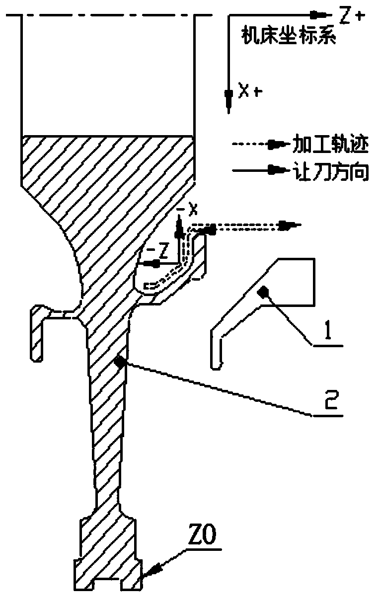
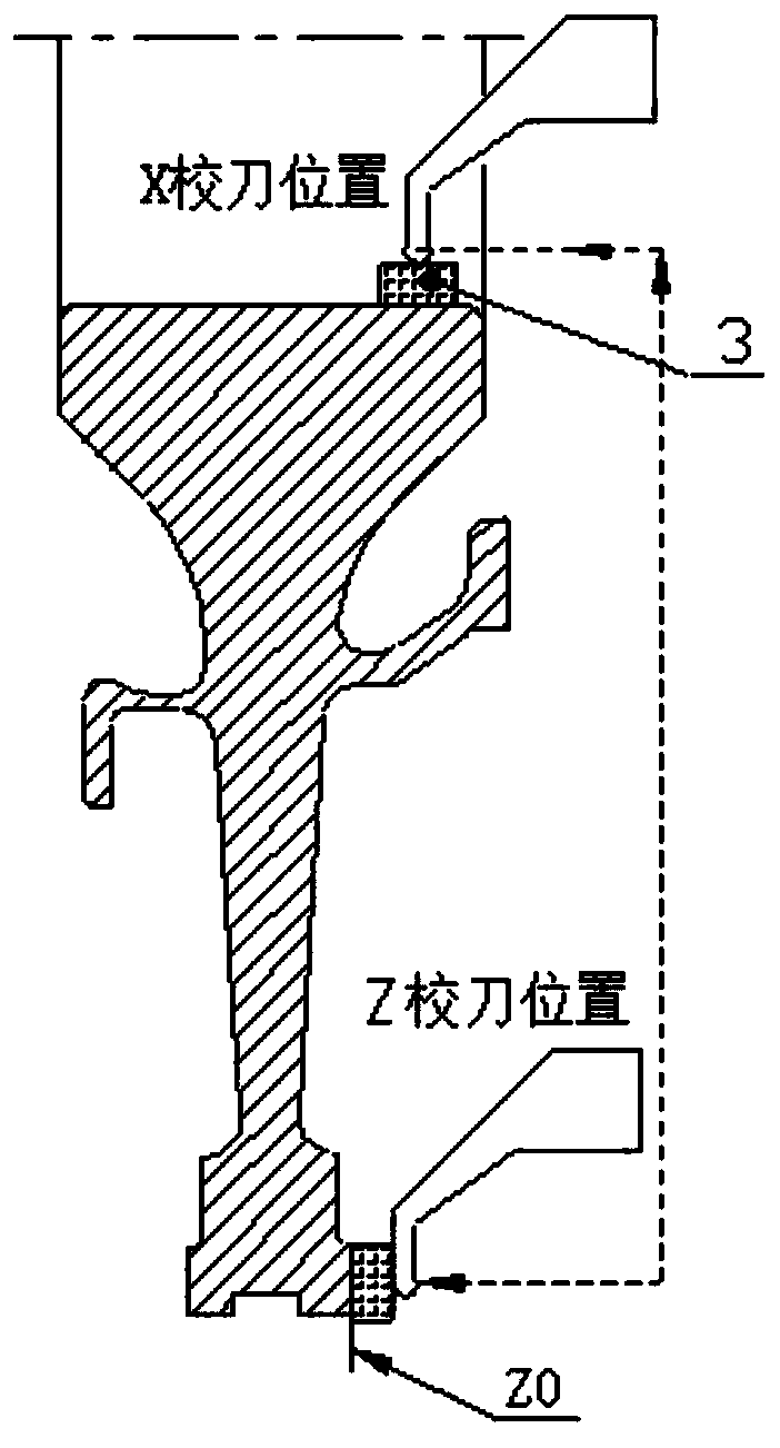
[0057] attached to figure 1 The cavity of the part shown is designed by the Siemens control system for the anti-mistake program of the turning process.

[0058] attached figure 1 The middle processing part is a part of the surface inside the cavity, the wall thickness tolerance of the right end surface is ±0.02mm, the tolerance of the left diameter is ±0.075mm, and the tolerance of the slope surface is ±0.1mm. The tool used is an elbow groove cutter. Due to the narrow size of the cutter head, considering its rigidity, there will be a certain amount of tool clearance during processing. The tool compensation direction and tool compensation amount follow the following principles: it is allowed to give the tool in the direction where there is no material, that is, no cutting, and the tool amount should not be too large, and must match the allowance. At the same time, the back of the tool must not interfere with the part. Therefore, the tool clearance direction in the X direction...

Embodiment 2

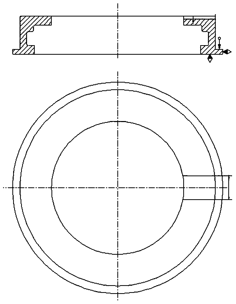
[0067] attached to image 3 The FANUC control system anti-error program design is carried out on both sides of the fine milling end face groove of the part shown.

[0068] Use the milling cutter 6 to process both sides of the end face groove, the cutter diameter is In order to ensure the surface roughness, the down milling method is selected for processing, and the G42 command is used for programming. The groove width tolerance of the part is〖24〗_0^(+0.05)mm. Considering the tool side edge wear, the minimum radius compensation is allowed to Since the margin on one side of the groove width after rough machining is 0.5mm, the maximum radius compensation is allowed up to The correct tool compensation range is Assign values ​​to #511 and #512 variables in the program. The groove depth is The margin at the bottom of the groove is 0.5mm, so the correct tool compensation range of the Z axis should be [-0.025,0.5], assign values ​​to #513 and #514 variables in the program, a...


PUM


Abstract

A method for preventing input errors of a numerical control machining tool setting value and a cutter compensation value includes cutter compensation value anti-misoperation and tool setting value anti-misoperation. According to the method, a cutter compensation range of each section of processing program can be associated with cutter compensation of an actually used cutter automatically, and a programmer only needs to care about the cutter compensation range of each program and does not need to consider the correspondence between a cutter compensation number and the tool compensation range atall. The programmer's labor intensity is reduced.

Description

technical field [0001] The invention belongs to the field of numerical control machining, and in particular relates to a method for preventing input errors of tool setting values ​​and tool compensation values ​​in numerical control machining. Background technique [0002] When CNC machining parts, the operator determines the relative position of the tool and the part to each coordinate axis through "tool setting", that is, determines the machining coordinate system. This process needs to input the tool setting values ​​of the machining coordinate system into the machine tool control system. During the machining process, it is necessary to comprehensively determine the tool compensation value according to the size of the spare part, the degree of tool wear, and the size of the dimensional tolerance, and input this compensation value into the control panel of the machine tool to precisely control the position of the tool to ensure the size required by the drawing. The tool se...

Claims


Application Information

Patent Timeline
Patent Type & Authority Patents(China)
IPC IPC(8): G05B19/19
Inventor 穆涛焦江涛何昊吴海涛赵冲冲王荣任海鹏夏野
Owner AECC AVIATION POWER CO LTD
Learn More