Negative Group Delay Circuit Based on Ferrite Circulator

A negative group delay and circulator technology, applied in circuits, electrical components, waveguide-type devices, etc., can solve the problems of difficult adjustment of negative group delay value, large circuit size, and application limitations of negative group delay circuits. The effect of simple realization method and simple circuit structure

Active Publication Date: 2020-03-31
10TH RES INST OF CETC
View PDF4 Cites 0 Cited by
  • Summary
  • Abstract
  • Description
  • Claims
  • Application Information

AI Technical Summary

Problems solved by technology

As the inductance value of the resonant unit increases, the frequency band of the phase jump in the frequency band with a positive phase change trend will be narrowed, which is not conducive to achieving phase compensation in a wider frequency band.
At the same time, due to the existence of high-frequency parasitic parameters of resistors, inductors, and capacitors, RLC circuits are only suitable for achieving negative group delay at low frequencies.
The disadvantage of the negative group delay circuit based on microstrip line coupling is that to realize the wiring of microstrip lines on the PCB, the processing technology of microstrip lines is relatively high, and the volume of the overall circuit is relatively large.
Therefore, the application of these negative group delay circuits is limited in situations where nonreciprocity and multi-channel negative group delay are required
In addition, the existing negative group delay circuit also faces problems such as limited operating frequency and bandwidth, and difficulty in adjusting the negative group delay value.

Method used


Image

  • Negative Group Delay Circuit Based on Ferrite Circulator
  • Negative Group Delay Circuit Based on Ferrite Circulator
  • Negative Group Delay Circuit Based on Ferrite Circulator

Examples


Embodiment Construction

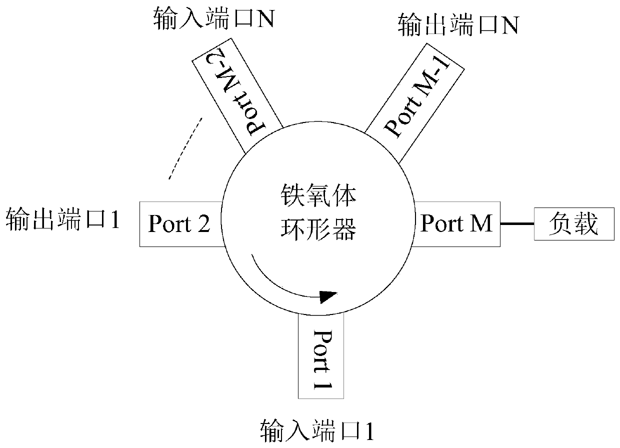
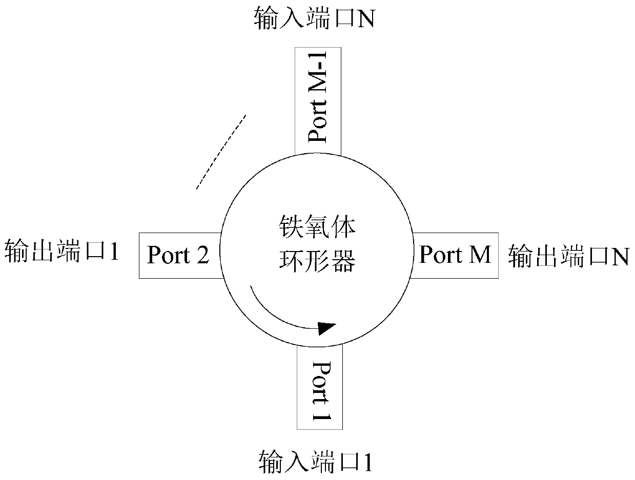
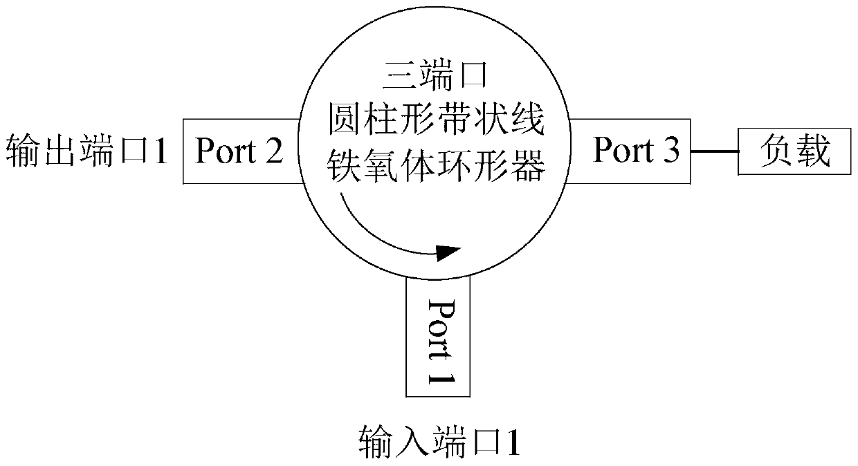
[0031]In the embodiment described below, the negative group delay circuit based on the ferrite circulator includes: including: N input ports, and N output ports corresponding to the N input ports, a ferrite with M ports Circulator and matching load, N signal input ports of negative group delay circuit and N output ports of ferrite circulator are connected with N input ports of ferrite circulator, ferrite circulator with n working modes The remaining P ports except the input and output ports are connected to matching loads; the N-way signals of the negative group delay circuit are respectively input from the N input ports of the circuit and output from the corresponding N output ports to generate N-way negative group time delay. The direction of the DC bias magnetic field in the ferrite circulator is perpendicular to the plane of the ring signal generated by it; the signal flow direction of the signal entering the signal input port of the negative group delay circuit is opposit...


PUM

PropertyMeasurementUnit
frequencyaaaaaaaaaa

Abstract

The invention discloses a ferrite circulator-based negative group delay circuit and aims to provide a negative group delay circuit of which a working center frequency, bandwidth, a negative group delay value and a negative group delay direction can be adjusted. According to the technical scheme, N signal input ports are connected with N output ports of a ferrite circulator, N signal output ports are connected with N input ports of the circulator, N paths of signals of the negative group delay circuit are respectively input from the N input ports of the circuit, N paths of negative group delayare output and generated from the N output ports, a DC bias magnetic field direction in the ferrite circulator is perpendicular to a annular signal plane generated by the DC bias magnetic field, a signal flowing direction, entering from the signal input ports, of a negative group delay circuit signal is opposite to an annular signal direction generated by the ferrite circulator, a negative group delay direction is reverse with a reverse direction of the DC bias magnetic field in the ferrite circulator, and the negative group delay value, the working center frequency and the negative group delay bandwidth are adjusted according to the size of the DC bias magnetic field.

Description

technical field [0001] The invention relates to a negative group delay generation circuit that can be applied in technical fields such as radio frequency microwave circuits, communication, navigation, measurement, and radar. Background technique [0002] In modern electronic systems such as radar, communication, and satellite navigation, group delay, which characterizes the phase linearity of signal transmission, has become an important design parameter and difficulty. For example, in the design of microwave radar phased array multi-channel transceiver components, a key design difficulty is that each component in the component must have accurate and consistent group delay characteristics; at the same time, in some microwave space test systems and navigation systems Among them, especially for equipment with extremely high precision performance requirements such as positioning and navigation systems, the group delay characteristic has a direct impact on the positioning accurac...

Claims


Application Information

Patent Timeline
Patent Type & Authority Patents(China)
IPC IPC(8): H01P1/38
Inventor 陈文兵
Owner 10TH RES INST OF CETC
Why Eureka
Try Eureka