

Cable duct penetrating device
A cable and threading pipe technology, which is applied in the field of cable laying construction equipment, can solve the problems of cable trench work, cable knotting, safety hazards, etc.
- Summary
- Abstract
- Description
- Claims
- Application Information
AI Technical Summary
Problems solved by technology
Method used
Image

Examples
Embodiment 1
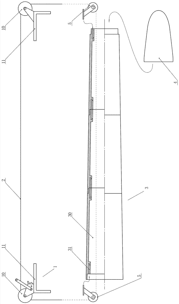
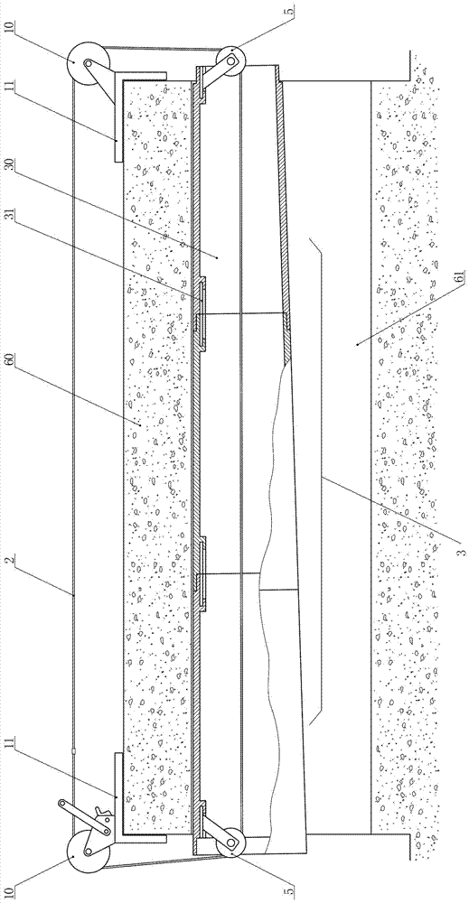
[0027] from Figure 1 ~ Figure 2 It can be seen that the technical solution of the present invention includes two sets of outer pulley supports 1, a traction rope 2, a threading pipe 3, at least two inner pulleys 5, and a cone cover 4;
[0028] The outer tube pulley support 1 includes a support pulley 10 and a support seat 11. The support seat 11 is in a right-angled structure, and the inner side of the 90° included angle of the main body of the support seat 11 is a fixed position on the ground (the level of its larger area The vertical section is used as a stable ground support, and the vertical section is stuck on the ditch cover or the edge of the shaft), and the supporting pulleys 10 are respectively fixed on the outside of the included angle of the main body of the supporting seat; at least one set of supporting pulleys 10 in the pulley support 1 outside the pipe is The main power wheel adopts a wire-controlled hand crank or a ratchet winch. It is also possible to use ac...
Embodiment 2
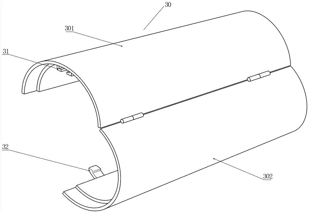
[0039] from image 3 It can be seen that the difference between this embodiment and Embodiment 1 is that each segment of the single casing 30 of the threading pipe 3 is composed of two arc-shaped plates, that is, the single casing 30 is formed along the direction of its center line. It is divided into an upper arc-shaped plate 301 and a lower arc-shaped plate 302. One side of the upper arc-shaped plate 301 and the lower arc-shaped plate 302 are hinged, and the other side is connected by a buckle 32 to form an openable structure, which is convenient for disassembly during construction. Install the threading pipe 3. The upper arc-shaped plate 301 and the lower arc-shaped plate 302 can also be made into a detachable structure, and the two arc-shaped plates are connected by buckles. This structural design makes the assembly and disassembly of the threading pipe 3 more convenient, and it is not affected by the length of the external cable of the cable trench during the trenching p...
PUM
 Abstract
Description
Claims
Application Information