
Vertical type cooling device and application method thereof

A cooling device, vertical technology, applied in the direction of fluidized bed furnace, etc., to achieve the effect of strengthening heat exchange effect, improving yield and improving cooling efficiency

Pending Publication Date: 2018-01-09
ZHONGYE-CHANGTIAN INT ENG CO LTD
View PDF7 Cites 0 Cited by
  • Summary
  • Abstract
  • Description
  • Claims
  • Application Information

AI Technical Summary

Problems solved by technology

[0008] In view of the above defects, the inventor developed a cooling system with high cooling efficiency, good cooling effect, recyclable sensible heat of some materials, and easy realization of large-scale by changing the cooling method, changing the horizontal type into a vertical type, and changing a single cooling medium into a composite cooling medium. A vertical sleeve-type composite high-efficiency cooling device for large-scale production, in order to make up for the defects of the existing technology

Method used


Image

  • Vertical type cooling device and application method thereof
  • Vertical type cooling device and application method thereof
  • Vertical type cooling device and application method thereof

Examples


Embodiment 1

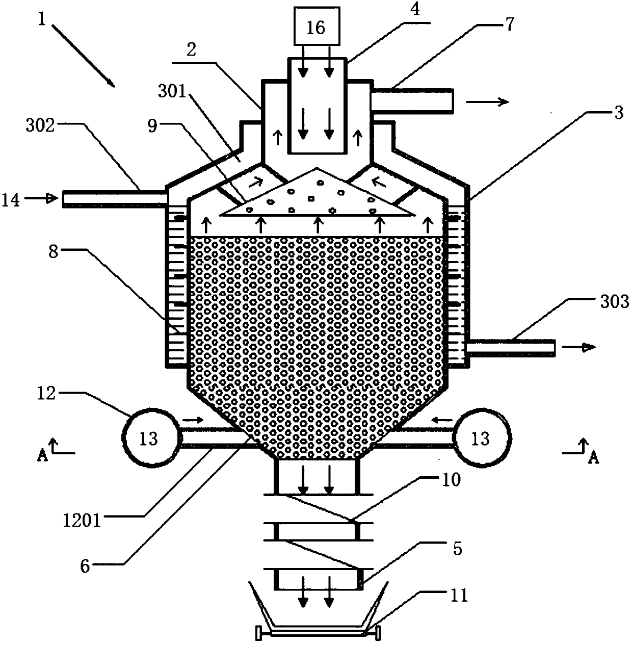
[0125] Such as figure 1 As shown, a vertical cooling device 1 includes a vertical cooling cylinder 2 . The top of the vertical cooling cylinder 2 is provided with a feeding port 4 . The bottom of the vertical cooling cylinder 2 is provided with a discharge port 5 . The periphery of the vertical cooling cylinder 2 is provided with a cooling jacket 3 . A space or gap 301 is provided between the cooling jacket 3 and the vertical cooling cylinder 2 . The cooling jacket 3 is a water cooling jacket. The upper part of the water cooling jacket is provided with an upper water inlet 302 of the water cooling jacket. The lower part of the water cooling jacket is provided with a water outlet 303 at the lower part of the water cooling jacket. Ribs 8 are provided in the voids or gaps 301 . The fins 8 are spiral fins. The fins 8 are arranged on the outer wall of the vertical cooling cylinder 2 . The outer diameter Φ of the vertical cooling cylinder is 8m. The height of the cylinder (...

Embodiment 2

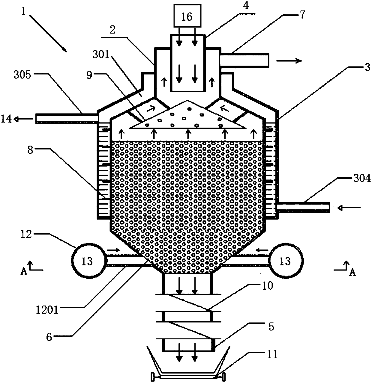
[0129] Such as figure 2 As shown, Example 1 is repeated, except that the cooling jacket 3 is another water-cooling jacket design, wherein the lower part of the water-cooling jacket is provided with a water inlet 304 at the lower part of the water-cooling jacket. The upper part of the water cooling jacket is provided with an upper water outlet of the water cooling jacket. The outer diameter Φ of the vertical cooling cylinder is 6m. The height of the cylinder (that is, the height difference from the inlet to the outlet) is 15m.

[0130] It takes 60-90 minutes to cool the direct reduced iron from 950°C-1000°C to 50°C by using the device.

Embodiment 3

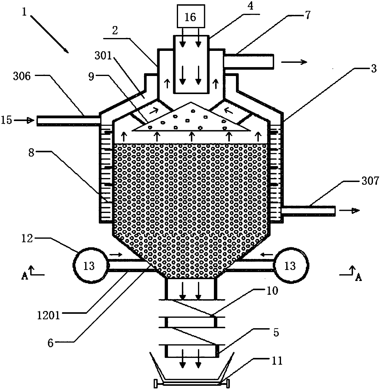
[0132] Such as image 3 Shown, repeat embodiment 1, only cooling jacket 3 is an air-cooled jacket. The upper part of the air-cooled jacket is provided with an upper air inlet 306 of the air-cooled jacket. The lower part of the air-cooled jacket is provided with an air outlet at the lower part of the air-cooled jacket. The outer diameter Φ of the vertical cooling cylinder is 7m. The height of the cylinder (that is, the height difference from the inlet to the outlet) is 16m.

[0133] It takes 90-110 minutes to cool the direct reduced iron from 950°C-1000°C to 50°C by using the device.


PUM


Abstract

The invention discloses a vertical type cooling device (1). The vertical type cooling device (1) comprises a vertical type cooling barrel (2). A feeding opening (4) is formed in the top of the vertical type cooling barrel (2), and a discharging opening (5) is formed in the bottom of the vertical type cooling barrel (2). The vertical type cooling device (1) is characterized in that a cooling jacket(3) is arranged at the periphery of the vertical type cooling barrel (2); and a gap or clearance (301) is formed between the cooling jacket (3) and the vertical type cooling barrel (2). The verticalsleeve type combined efficient cooling device and an application method thereof are high in cooling efficiency and good in cooling effect, and large-scale mass production can be achieved easily.

Description

technical field [0001] The invention relates to a cooling device and its use method, in particular to a vertical cooling device and its use method in the field of mining and metallurgy, and in particular to a vertical water-air composite cooling method for DRI and its device. Background technique [0002] Direct Reduced Iron (DRI-Direct Reduced Iron, DRI for short) refers to a low-carbon porous substance formed by refined iron powder or iron oxide reduced in a furnace at a low temperature. Its chemical composition is stable and its impurity content is low. Unlike sinter and oxidized pellets that are fed into blast furnace ironmaking, most of the direct reduction iron ore is used as raw material for electric furnace and converter steelmaking, which can increase the uniformity of steel and improve the physical properties of steel, so as to achieve high-quality production steel purpose. Direct reduced iron is not only a substitute for high-quality steel scrap, but also an indi...

Claims


Application Information

Patent Timeline
IPC IPC(8): C21B13/00
Inventor 周浩宇贺新华
Owner ZHONGYE-CHANGTIAN INT ENG CO LTD
Learn More