Eureka AIR delivers breakthrough ideas for toughest innovation challenges, trusted by R&D personnel around the world.

Cloth cutting mechanism

The technology of a cloth cutting mechanism and a conductive rod, which is applied to the cutting of textiles, papermaking, and textile materials, can solve the problems of complex structure, low work efficiency and high cost of the cutting machine, so as to reduce equipment costs and labor costs, and reduce cutting costs. The effect of fast speed and increased equipment cost

Pending Publication Date: 2018-01-09
湖州凯尔服饰有限公司
View PDF0 Cites 0 Cited by
  • Summary
  • Abstract
  • Description
  • Claims
  • Application Information

AI Technical Summary

Problems solved by technology

[0005] The content of the present invention is to provide a cloth cutting mechanism, which can overcome the defects of complex structure, high cost and low work efficiency of existing cutting machines

Method used


Image

  • Cloth cutting mechanism
  • Cloth cutting mechanism

Examples


Embodiment 1

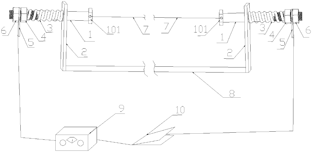
[0022] Such as figure 1 As shown, the present embodiment provides a kind of cloth cutting mechanism, and it comprises workbench 8, and workbench 8 is arranged horizontally, and the knife rest plate 2 that is vertically installed on the two ends of workbench 8, of course, knife rest plate 2 can be fixed by bolts , can also be tied to the workbench 8 or the table by welding or tying, the knife rest plate 2 is an insulating board, a wooden board or a plastic plate, the through hole provided on the top of the knife rest plate 2, the conductive rod 1 is a metal rod, and one end A cylindrical cap 101 with a diameter greater than the diameter of the through hole of the knife rest plate 2 is provided, and the other end of the conductive rod 1 is provided with a screw thread. The cylindrical cap of the conductive rod 1 is provided with a through hole connected with the heating wire 7, and the conductive rod 1 passes through. Through the through hole on the knife rest plate 2, the part ...

Embodiment 2

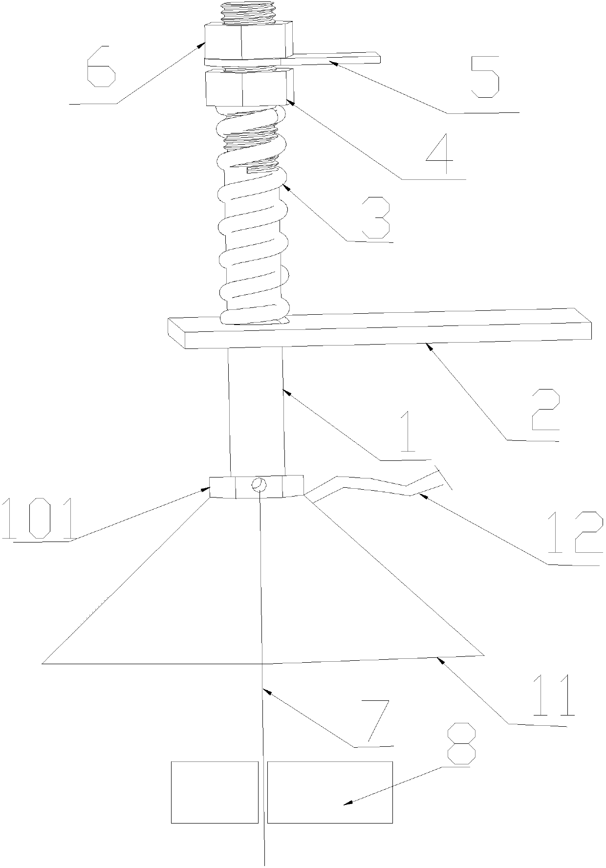
[0025] Such as figure 2 As shown, the difference between this embodiment and Embodiment 1 is that the electric heating wire 7 is a molybdenum wire placed vertically, and the connection between the upper end of the electric heating wire 7 and the conductive rod 1 is provided with an exhaust hood 11, and the exhaust hood 11 is bolted to a conductive Rod 1 cylinder rises up, and exhaust hood 11 is connected with exhaust fan by exhaust pipe 12, and described exhaust hood 11 is made of transparent material. To cut the fabric, one end of the fabric is pulled up and passed through the heating wire 7 for thermal cutting. The gas generated during cutting can be extracted through the exhaust hood head 11 and the exhaust pipe 12. Adjusting the current can make the heating wire 7 produce different temperatures. In this way, fabrics of different thicknesses and materials can be cut, and the cutting speed is fast and there is no burr.


PUM


Abstract

The invention belongs to the technical field of cloth processors, and particularly relates to a cloth cutting mechanism. The mechanism comprises a workbench, a current regulator and a switch, two knife rest plates are arranged on the workbench, and conducting rods are arranged at the upper ends of the knife rest plates; the conducting rods can slide relative to the knife rest plates, the conducting rods are connected with heating wires, and the heating wires and the switch are in series connection with the current regulator; the heating wires provide elastic parts with elasticity. For cuttingof some cloth raw edges, the cloth cutting mechanism is high in working efficiency, cutting is in order, and the cloth cutting mechanism cannot greatly increase the device cost.

Description

technical field [0001] The invention belongs to the technical field of cloth processors, and in particular relates to a cloth cutting mechanism. Background technique [0002] Cloth cutting machines are widely used for cutting cloth, leather, cotton textiles, cardboard and other similar materials. The traditional cloth cutting machine generally uses a high-speed rotating circular knife to cut the cloth to be cut by sliding cutting. The cut section is prone to burrs, fibers fall off, and has a complex structure and dangerous operation; [0003] Some of the existing cloth cutting machines use circular heating wires of different specifications to fuse the cloth. The service life of the circular heating wires is short and the cost is high. For some small factories or companies that do not need too precise cutting, adding such a machine will greatly increase the cost input , and the work efficiency is not high. [0004] For some raw edges of fabrics, scissors are generally used ...

Claims


Application Information

Patent Timeline
IPC IPC(8): D06H7/22
Inventor 沈雪红
Owner 湖州凯尔服饰有限公司
Why Eureka
Eureka Blog
Learn More