
BOG recycling and nitrogen liquefying system and technological method

A technology of nitrogen gas and vaporizer, which is applied in the field of BOG recovery and nitrogen liquefaction system, can solve the problems of refrigerant ratio requiring additional equipment, inability to handle BOG recovery, further verification and other problems, so as to improve energy utilization efficiency, convenient operation, low cost effect

Active Publication Date: 2018-01-09
YANGTZE UNIVERSITY
View PDF9 Cites 5 Cited by
  • Summary
  • Abstract
  • Description
  • Claims
  • Application Information

AI Technical Summary

Problems solved by technology

[0007] (1) Mixed refrigerant BOG recondensation process, that is, using multi-component light hydrocarbons as refrigerants, and using refrigeration cycles to condense and recover BOG, but this process has many heat exchange equipment and complicated processes, and additional equipment is required for the ratio of refrigerants
[0008] (2) Multi-stage compression BOG recondensation process, that is, the use of multi-stage compression technology to reduce compression power consumption and improve operational flexibility, but this process cannot handle BOG recovery under shutdown conditions. There are still limitations in the case of
[0009] (3) The BOG recondensation process with an expander uses the gasified high-pressure natural gas to drive the output shaft work of the expander to supply the high-pressure pump, so as to achieve the purpose of LNG boosting while consuming almost no additional energy. However, this process is due to its higher The pressure range puts higher requirements on the process pipeline and booster equipment, and the feasibility under fluctuating conditions needs to be further verified

Method used


Image

  • BOG recycling and nitrogen liquefying system and technological method

Examples


Embodiment Construction

[0037] The implementation of the present invention will be described in detail below in conjunction with the examples of implementation, but they do not constitute a limitation of the present invention, and are only examples. At the same time, the advantages of the present invention will become clearer and easier to understand.

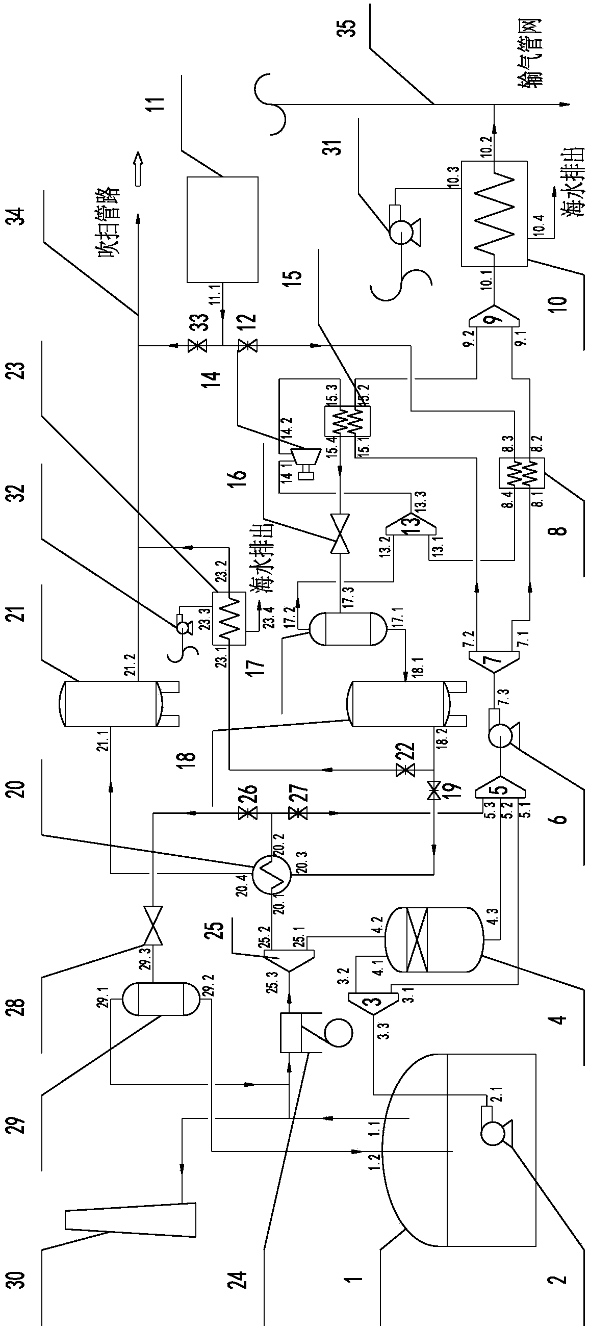
[0038] Such as figure 1 A BOG recovery and nitrogen liquefaction system of the present invention is shown, comprising an LNG storage tank 1, a pump in the tank 2, a first LNG distributor 3, a recondenser 4, a first LNG mixer 5, a high-pressure pump 6, a second LNG distributor 7, first heat exchanger 8, second LNG mixer 9, LNG vaporizer 10, PSA nitrogen generator 11, first valve 12, nitrogen mixer 13, nitrogen compressor 14, second heat exchanger Device 15, nitrogen separator 17, liquid nitrogen tank 18, second valve 19, BOG-liquid nitrogen heat exchanger 20, nitrogen tank 21, third valve 22, liquid nitrogen vaporizer 23, BOG compressor 24, BOG distri...


PUM


Abstract

The invention discloses a BOG recycling and nitrogen liquefying system and technological method. According to the BOG recycling and nitrogen liquefying system, two-grade cooling is conducted on nitrogen prepared by a PSA nitrogen-making device through LNG cold energy, so that the nitrogen is liquefied and stored; in the BOG liquefying system, BOG is pressurized through a compressor and then conducts heat exchange with the liquid nitrogen, so that the BOG is liquefied, the liquid nitrogen absorbs heat and is gasified and stored in a nitrogen storage tank, and the nitrogen can be used for station blowing; the liquefied BOG enters a high-pressure pump to be output, or the liquefied BOG is decompressed through throttling and then enters a separator, the liquid-phase BOG is fed into the bottomof a LNG storage tank to be stored, and the gas-phase BOG enters a BOG compression cycle. By the adoption of the BOG recycling and nitrogen liquefying technological method, the problem that BOG recycling is difficult when the output amount of an LNG receiving station is low is solved, the demand for the low-temperature blowing technology of the station is met, the energy utilization rate is improved since LNG cold energy is utilized, and the equipment investment is reduced since existing PSA nitrogen making equipment of the LNG station is utilized.

Description

technical field [0001] The invention relates to the technical field of LNG storage and transportation, in particular to a BOG recovery and nitrogen liquefaction system and process method. Background technique [0002] With the increasingly prominent problem of air pollution, my country's demand for clean energy is becoming more and more urgent. LNG (liquefied natural gas), as a form of storage and transportation of natural gas, a clean energy source, is widely used in gas protection and peak shaving in coastal cities. my country's LNG receiving stations are widely distributed in various coastal cities, and a large amount of BOG (flash steam) generated during their operation poses a threat to the safety of receiving stations. BOG is a gas formed by LNG heated and vaporized. Due to the limitation of insulation materials, it is inevitable that heat will infiltrate from the outside, causing LNG to evaporate when heated. With the continuous invasion of heat, the mass of the gas...

Claims


Application Information

Patent Timeline
Patent Type & Authority Applications(China)
IPC IPC(8): F25J3/06
Inventor 张引弟薛鹏伍丽娟沈秋婉史宝成
Owner YANGTZE UNIVERSITY
Learn More