Straight fin for coke oven ascending pipe raw coke oven gas waste heat recycling and heat taking device and heat taking device

A waste heat recovery and raw gas technology, which is applied in the coke oven rising tube waste heat boiler power generation device, coke oven rising tube raw gas waste heat recovery heat extraction device with straight fins, coke oven rising tube waste gas waste heat recovery heat recovery device field, It can solve problems such as the separation of the straight fin and the wall of the cylinder, the failure of the heat transfer area of ​​the straight fin, and the different expansion conditions, etc., and achieve the effect of low cost, simple structure and extended service life

Active Publication Date: 2018-01-09
NANJING HUADIAN ENERGY SAVING & ENVIRONMENTAL PROTECTION EQUIP
View PDF4 Cites 2 Cited by
  • Summary
  • Abstract
  • Description
  • Claims
  • Application Information

AI Technical Summary

Problems solved by technology

If the straight fins of the conventional rectangular thin plate structure are directly welded to the wall of the raw gas channel, for the top of each straight fin, the thermal expansion rate of the lower part is greater than that of the upper part. At the same time, at the same height position, the fin top The thermal expansion rate of the straight fin is greater than that of the root. Therefore, for the entire straight fin, there will be a more complicated and different expansion situation everywhere, and it is inconsistent with the tube wall. Eventually, the weld between the straight fin and the tube wall will be torn due to Cracked and disengaged, making the heat transfer area of ​​the straight fins invalid

Method used


Image

  • Straight fin for coke oven ascending pipe raw coke oven gas waste heat recycling and heat taking device and heat taking device
  • Straight fin for coke oven ascending pipe raw coke oven gas waste heat recycling and heat taking device and heat taking device
  • Straight fin for coke oven ascending pipe raw coke oven gas waste heat recycling and heat taking device and heat taking device

Examples


Embodiment 1

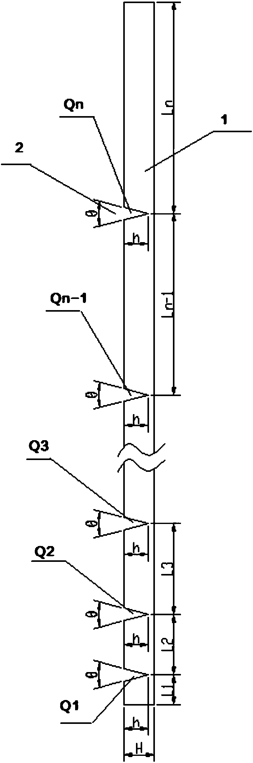
[0028] Straight fins for waste heat recovery device of waste gas in coke oven riser, see figure 1 , including a straight fin body (1) and a group of V-shaped cutouts (2) arranged on the straight fin body (1); the depth h of the V-shaped cutout (2) is smaller than that of the straight fin body (1) Width H; in the longitudinal direction of the straight fin body (1), the distance between adjacent V-shaped cutouts (2) increases from bottom to top.

[0029] In the longitudinal direction of the straight fin body (1), the set of V-shaped cutouts (2) are sequentially numbered Q1 to Qn-1 from bottom to top; the distance from Q1 to the bottom end of the straight fin body (1) is L1, The distance between adjacent V-shaped notches (2) is L2 to Ln-1 from bottom to top, and the distance from Qn-1 to the top is Ln; L1 to Ln form an arithmetic sequence, and optionally, the values ​​of L1 to Ln increase evenly The purpose of the present invention can be achieved.

[0030] The opening angles θ...

Embodiment 2

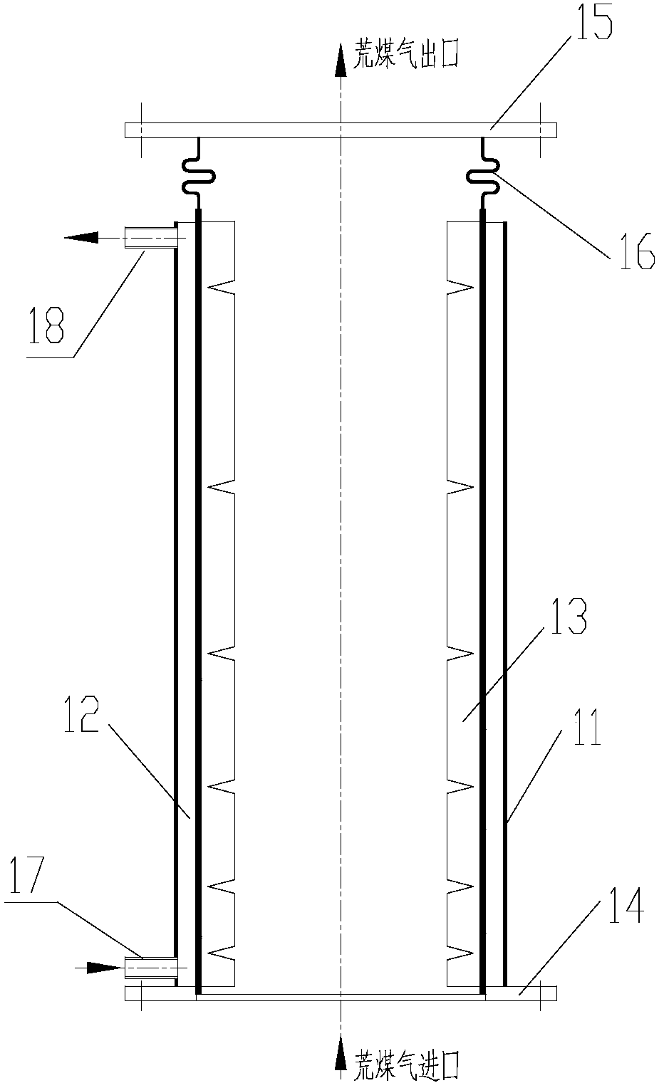
[0036] Coke oven riser waste gas waste heat recovery device, see figure 2, comprising a raw gas pipeline (11), a heat exchange tube (12), a group of straight fins (13) of embodiment 1; the heat exchange tube (12) is located on the outer wall of the raw gas pipeline (11); the described A group of straight fins (13) are arranged on the inner wall of the raw gas pipeline (11); the raw gas inlet of the raw gas pipeline (11) is provided with a lower flange (14), and the raw gas outlet is provided with an upper flange (15); the upper part of the raw gas pipeline (11) is provided with an expansion joint (16); the lower part of the heat exchange tube (12) is provided with a heat-taking medium inlet (17), and the upper part is provided with a heat-taking medium outlet (18) .

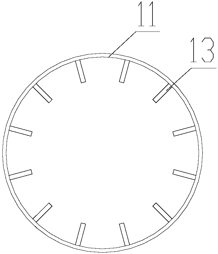
[0037] In the present invention, the set of straight fins (13) are vertically arranged at the same distance along the inner wall of the raw gas pipeline (11), see image 3 Optionally, whether the set of straig...

Embodiment 3

[0043] Coke oven rising tube waste heat boiler power generation device, see Figure 4 , including a waste heat boiler (22), a heat medium pump (23), a steam turbine (24), a water pump (25), a generator (26) and a set of coke oven riser gas waste heat recovery heat recovery device (21 ); the waste heat boiler (22) includes a hot coal pipeline and a steam-water circulation pipeline; The coal pipeline and the heat medium pump (23) are connected in sequence, and the heat medium pump (23) is connected with the heat medium inlet (17) of each coke oven rising pipe raw gas waste heat recovery heat recovery device (21); the waste heat boiler ( The steam-water circulation pipeline of 22), the steam turbine (24) and the water pump (25) are sequentially connected to form a loop; the generator (26) is connected to the steam turbine (24).

[0044] Taking 1.3 million tons / year coking as an example, the raw gas temperature is 800°C. At present, the temperature is lowered to 70°C by spraying ...


PUM


Abstract

The invention provides a straight fin for a coke oven ascending pipe raw coke oven gas waste heat recycling and heat taking device. The straight fin comprises a straight fin body (1) and a set of V-shaped notches (2) formed in the straight fin body (1). The depth h of the V-shaped notches (2) is smaller than the width H of the straight fin body (1). In the longitudinal direction of the straight fin body (1), the distances between the adjacent V-shaped notches (2) are increased from bottom to top. The invention further provides a heat taking device comprising the straight fin and a power generation device. The straight fin is simple in structure, low in cost and convenient to use, the heat transmitting performance of the raw coke oven gas side is greatly enhanced, and the wall face temperature is increased. Meanwhile, the width, the angle and the height-direction distance of the V-shaped notches in the top end of the straight fin are determined according to temperature field distribution during device usage, and when the device is used, the longitudinal swelling amount of the top end of the fin is smaller than or equal to the notch width, and after total expansion in the height direction, the straight fin is still kept in a flat rectangle and cannot disengage from the inner barrel wall, and the service life is greatly prolonged.

Description

technical field [0001] The invention belongs to the technical field of boiler equipment, and in particular relates to a straight fin used for a coke oven ascending tube raw gas waste heat recovery heat recovery device, and also relates to a coke oven rising tube waste gas waste heat recovery heat recovery device including the above straight fins. The utility model relates to a coke oven ascending tube waste heat boiler power generation device including the above-mentioned straight fins. Background technique [0002] Fins are the basic elements of plate-fin heat exchangers, and the heat transfer process in plate-fin heat exchangers is mainly accomplished through the heat conduction of the fins and the convective heat transfer between the fins and the fluid. The fins are the secondary heat exchange surface, which can not only expand the heat transfer area, improve the compactness and heat transfer efficiency of the heat exchanger, but also support the core and improve the stre...

Claims


Application Information

Patent Timeline
Patent Type & Authority Applications(China)
IPC IPC(8): F28F3/02F22B1/18C10B27/00C10B41/08
CPCC10B27/00C10B41/08F22B1/18F28F3/022F28F2215/08C10B27/06F22B1/1869F22B9/04F22B9/18F22B37/103F27D17/004F27D2017/006F28D1/06F28D7/106F28D2021/0056F28F1/40F28F2265/26Y02P20/129C10B3/02
Inventor 刘小平陆建宁李菊香董人和杨桂兰郑璇
Owner NANJING HUADIAN ENERGY SAVING & ENVIRONMENTAL PROTECTION EQUIP
Why Eureka
Try Eureka