
Optical fiber sensing system

An optical fiber sensing system and sensor technology, applied in the direction of using optical devices to transmit sensing components, etc., can solve the problems of being susceptible to environmental interference, inflexible adjustment, and expensive systems, so as to reduce costs and eliminate interference from environmental noise Effect

Active Publication Date: 2018-01-09
GUANGZHOU MARINE GEOLOGICAL SURVEY +1
View PDF7 Cites 15 Cited by
  • Summary
  • Abstract
  • Description
  • Claims
  • Application Information

AI Technical Summary

Problems solved by technology

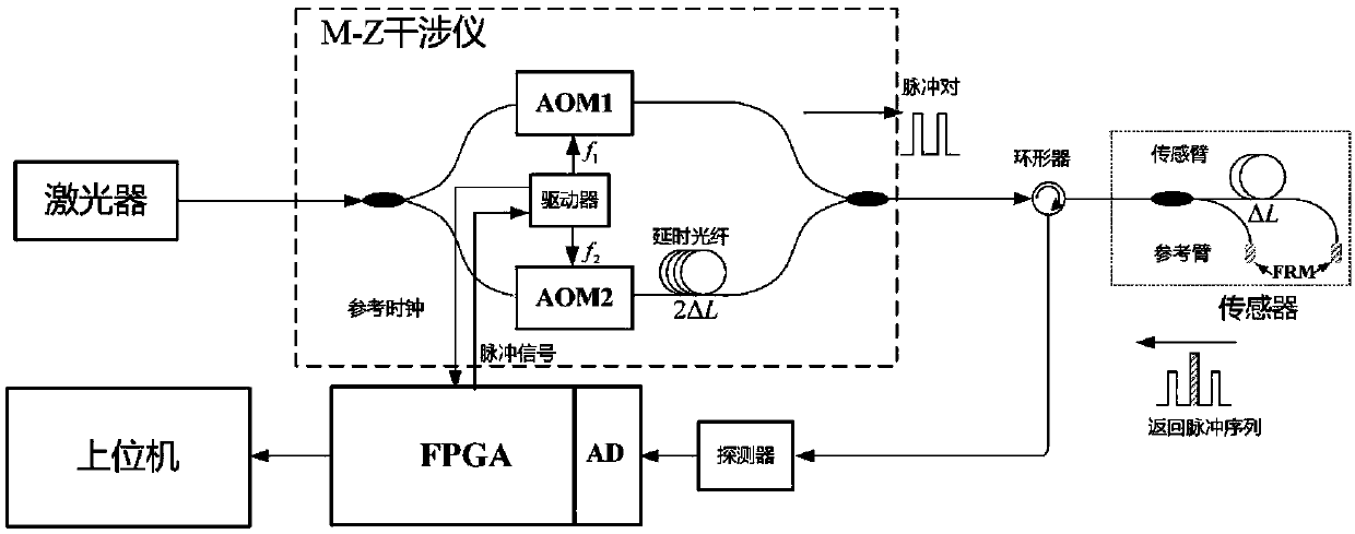
[0005] In order to overcome the deficiencies of the prior art, the object of the present invention is to provide an optical fiber sensing system, which overcomes the disadvantages of the traditional DDH scheme, such as expensive system, easy to be affected by environmental interference, and inflexible adjustment.

Method used


Image

  • Optical fiber sensing system
  • Optical fiber sensing system
  • Optical fiber sensing system

Examples


Embodiment Construction

[0033] Below, in conjunction with accompanying drawing and specific embodiment, the present invention is described further:

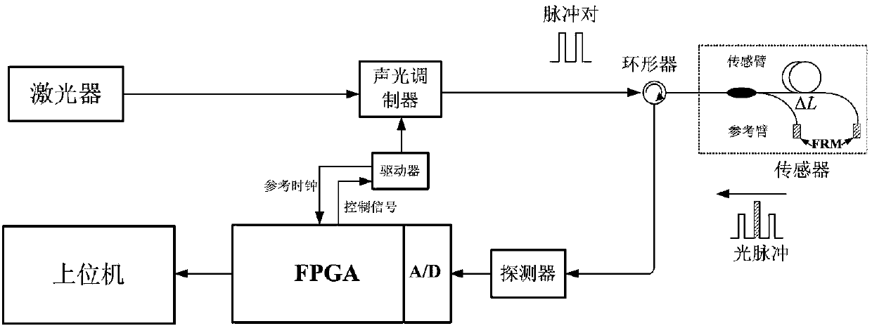
[0034] Such as figure 2 As shown, the invention provides a kind of optical fiber sensing system, comprising:

[0035] a laser for emitting continuous light of a specified frequency;

[0036] an acousto-optic modulator for receiving continuous light and modulating it into a differential time-delayed pulse pair;

[0037] A circulator is used to receive the differential delayed pulse pair and output it to the sensor;

[0038] A sensor for processing the differentially delayed pulses output by the circulator to form an optical pulse and send it to the detector through the circulator;

[0039] a detector for receiving optical pulses to form an interference optical signal, and converting the interference optical signal into an interference electrical signal and sending it to an analog-to-digital converter;

[0040] An analog-to-digital converter (A / D), w...


PUM


Abstract

The invention provides an optical fiber sensing system. The system comprises a laser which is used for transmitting continuous light of a designated frequency, an acousto-optic modulator which is usedfor receiving the continuous light and modulating the continuous light into a differential delay pulse pair, a circulator which is used for receiving the differential delay pulse pair and outputtingthe differential delay pulse pair to a sensor, the sensor which is used for processing the differential delay pulses output by the circulator to form a light pulse and sending the light pulse to a detector through the circulator, the detector which is used for receiving the light pulse to form an interference light signal, converting the interference light signal into an interference electrical signal and sending the interference electrical signal to an analog-digital converter, the analog-digital converter which is used for converting the interference electrical signal into an interference digital signal and sending the interference digital signal to an FPGA module, and the FPGA module which is used for controlling a driver to generate radio frequency pulse signals of different frequencies, and carrying out phase algorithm processing according to the interference digital signal to acquire phase information. According to the invention, the acousto-optic modulator is used, which effectively reduces the cost; and a front-end MZ interferometer is eliminated, which can effectively eliminate the interference of the environmental noise.

Description

technical field [0001] The invention relates to the field of optical fiber sensing, in particular to an optical fiber sensing system based on a single acousto-optic modulator. Background technique [0002] As a new type of sensor, fiber optic sensors have the advantages of anti-electromagnetic interference, high sensitivity, and large-scale multiplexing. They are increasingly used in vibration detection, perimeter security, oil field development, and building health monitoring. In order to improve the cost performance of the optical fiber sensing system, it is necessary to multiplex multiple optical fiber sensors to form an array or network, such as the submarine array cable (Ocean Bottom Cable, OBC) used in the field of underwater acoustic detection, and the vertical seismic profile ( Vertical Seismic Profiling, VSP) detector array, etc. Multiplexing methods that can be used here include time division multiplexing, space division multiplexing, wavelength division multiplex...

Claims


Application Information

Patent Timeline
Patent Type & Authority Applications(China)
IPC IPC(8): G01D5/353
Inventor 梁前勇张敏何涛董一飞
Owner GUANGZHOU MARINE GEOLOGICAL SURVEY
Learn More