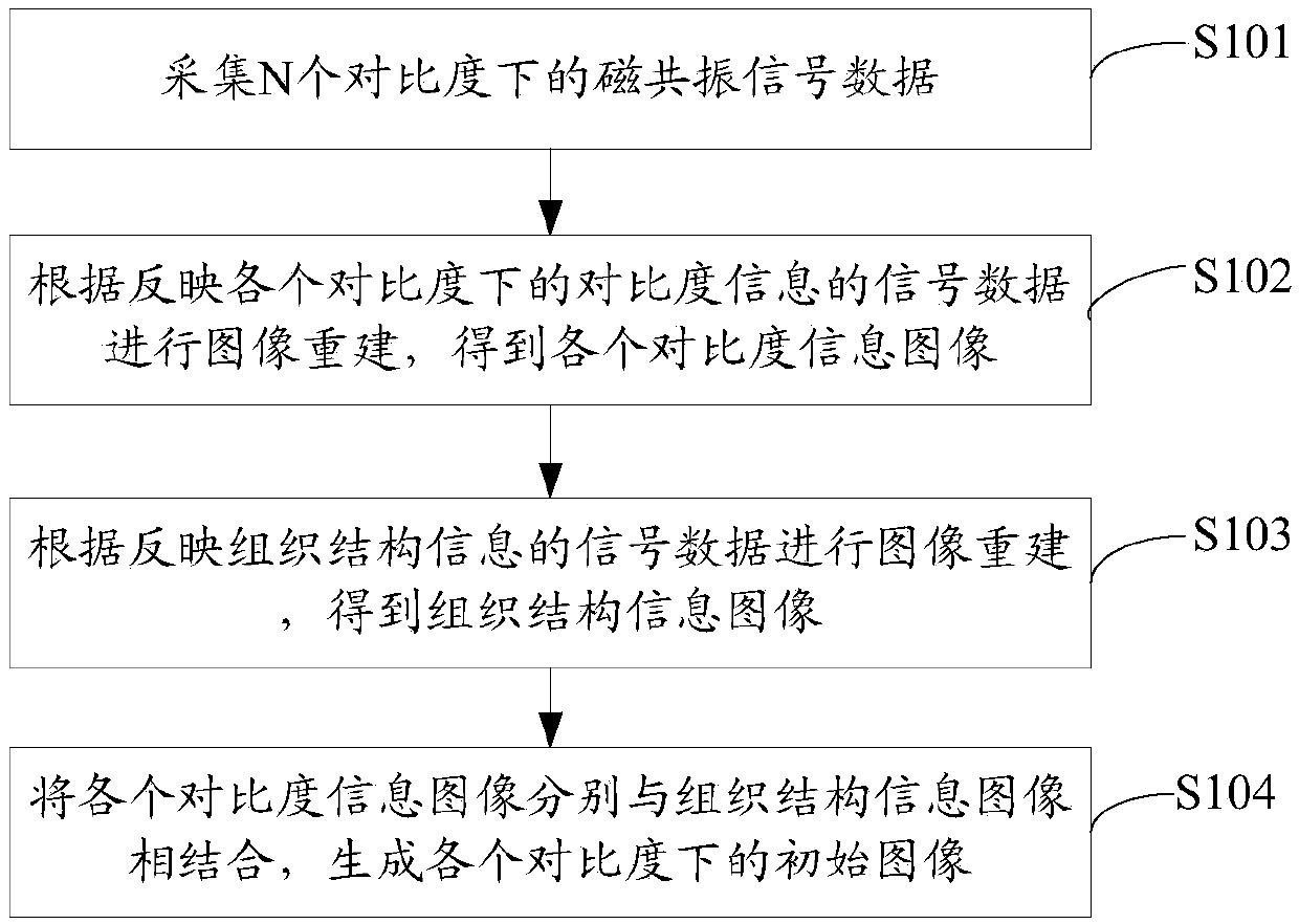
Magnetic resonance multi-contrast image reconstruction method and device
An image reconstruction and contrast technology, applied in the field of image processing, can solve problems such as image contrast pollution and inaccurate image results, and achieve the effect of improving accuracy
- Summary
- Abstract
- Description
- Claims
- Application Information
AI Technical Summary
Problems solved by technology
Method used
Image
Examples
Embodiment approach 1
[0052] Before introducing the first implementation mode, first introduce the prerequisites for the implementation of the first implementation mode.
[0053] In the magnetic resonance multi-contrast image, the magnetic resonance signal reflecting tissue structure information is a high-frequency signal in the frequency space, and the signal located in the peripheral area filling the K-space is a signal reflecting tissue structure information. A larger number of signals is required to reflect organizational structure information. The signal reflecting the contrast information is a low-frequency signal in the frequency space, therefore, a small number of signals can reflect the contrast, so that the magnetic resonance signal data reflecting the contrast signal can be obtained by only scanning the signal filling the central area of K space.
[0054] Among them, the K space refers to the magnetic resonance signal space (original data space), that is, the Fourier transform space. T...
Embodiment approach 2
[0105] Embodiment 2 has many similarities with Embodiment 1. For the sake of brevity, Embodiment 2 focuses on the differences between the two. For the similarities, please refer to the relevant description of Embodiment 1.
[0106] Figure 4 It is a schematic flow chart of Embodiment 2 of the present application. Such as Figure 4 As shown, the second embodiment also includes a data acquisition process and an image reconstruction process, wherein the data acquisition process includes the following steps:
[0107] S401 to S402 are the same as steps S301 to S302 in Embodiment 1, and for the sake of brevity, no detailed description is given here.
[0108] S403. Acquire the magnetic resonance signal data of the central region in the frequency space of each contrast according to the set magnetic resonance scanning parameters, wherein the magnetic resonance signal data of the central region in the frequency space of each contrast reflect each contrast The signal data under the co...
Embodiment approach 3
[0119] Figure 5 It is a schematic flow chart in Embodiment 3 of the present application. Such as Figure 5 As shown, this embodiment 3 includes the following steps:
[0120] S501, setting the magnetic resonance scanning parameters under each contrast.
[0121] S502. According to the set magnetic resonance scanning parameters, adopt the acquisition method of full sampling of the sampling points in the central area of K space according to the preset acquisition trajectory to separately acquire the magnetic resonance signal data under each contrast, the magnetic resonance signal data under each contrast Including magnetic resonance signal data in the central area of K-space and magnetic resonance signal data in the peripheral area of K-space; the preset acquisition trajectory is a spiral trajectory or a radial trajectory;
[0122] Among them, the magnetic resonance signal data in the central area of K space is the signal data reflecting the contrast The magnetic res...
PUM
 Abstract
Description
Claims
Application Information
 - R&D
- Intellectual Property
- Life Sciences
- Materials
- Tech Scout
- Unparalleled Data Quality
- Higher Quality Content
- 60% Fewer Hallucinations
Browse by: Latest US Patents, China's latest patents, Technical Efficacy Thesaurus, Application Domain, Technology Topic, Popular Technical Reports.
© 2025 PatSnap. All rights reserved.Legal|Privacy policy|Modern Slavery Act Transparency Statement|Sitemap|About US| Contact US: help@patsnap.com


