Compressor piston for balancing reciprocating motion inertia force

A technology of reciprocating motion and inertial force, which is applied in the direction of machines/engines, mechanical equipment, liquid variable displacement machinery, etc., can solve problems such as difficult to reach low-pressure pistons, compressors cannot run smoothly, and piston quality is not balanced, and achieve structural Reasonable, balanced quality, and the effect of ensuring smooth operation

Inactive Publication Date: 2018-01-12
BENGBU GAOKE ENERGY EQUIP
View PDF13 Cites 28 Cited by
  • Summary
  • Abstract
  • Description
  • Claims
  • Application Information

AI Technical Summary

Problems solved by technology

However, sometimes due to the large bore of the low-pressure stage and the heavy weight of the piston, while the bore of the high-pressure stage is small, it is difficult for the pistons of

Method used


Image

  • Compressor piston for balancing reciprocating motion inertia force
  • Compressor piston for balancing reciprocating motion inertia force
  • Compressor piston for balancing reciprocating motion inertia force

Examples


Embodiment 1

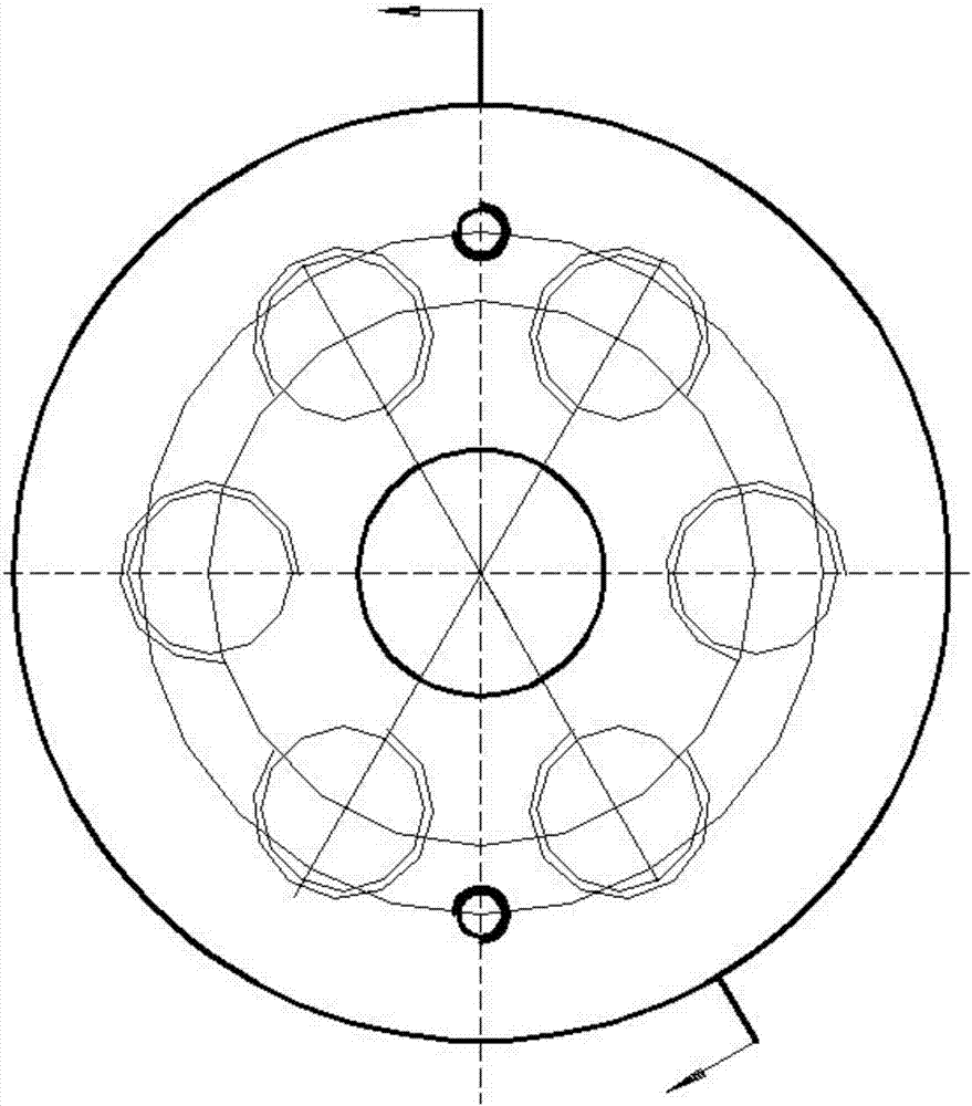
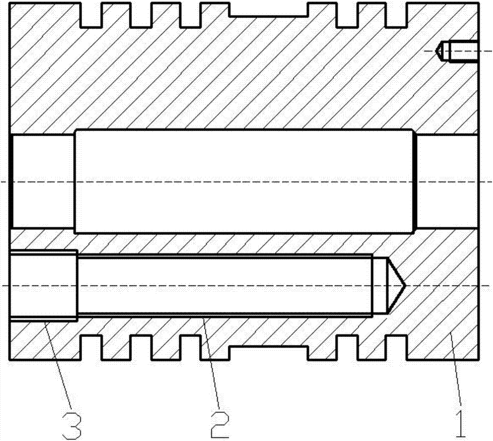
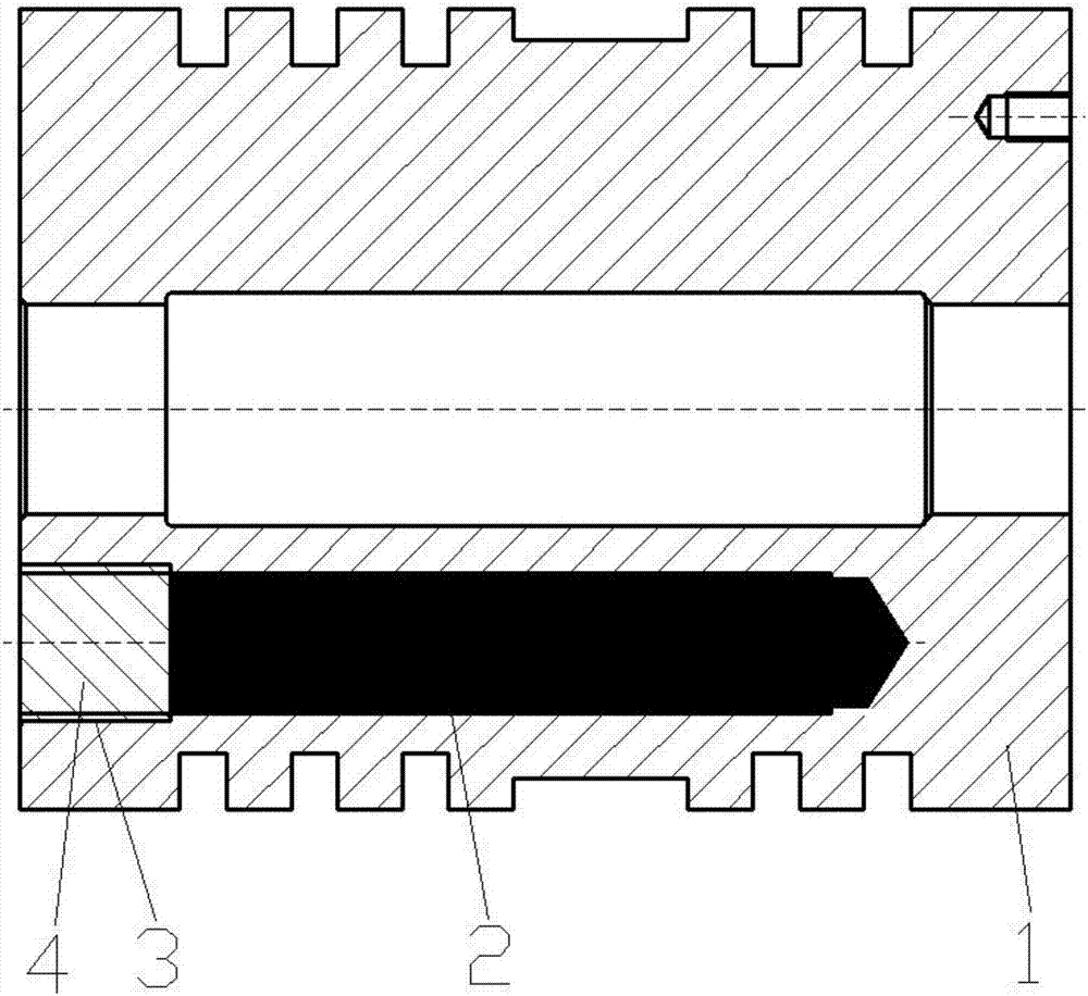
[0018] Reference Figure 1-3 , A compressor piston that balances the inertial force of reciprocating motion, comprising a piston body 1. The upper end surface of the piston body 1 is provided with two symmetrical screw holes, and the lower end surface of the piston body 1 is provided with 6 threaded holes. The threaded holes are perpendicular to the lower end surface of the piston body, and the threaded holes are counterbored structures, including small diameter threaded holes 2 and large diameter threaded holes 3. The threaded holes are distributed in a circular array based on the center of the through holes on the upper and lower ends of the piston body 1 .

[0019] The threaded hole is a counterbore structure, and the small diameter threaded hole 2 is drilled on the lower end surface of the piston body 1 first, and then the small diameter threaded hole 2 is enlarged in diameter, and the large diameter threaded hole 3 is drilled. Use lead as the filler, pour lead into the smal...

Embodiment 2

[0021] Reference Figure 1-3 , A compressor piston that balances the inertial force of reciprocating motion, comprising a piston body 1. The upper end surface of the piston body 1 is provided with two symmetrical screw holes, and the lower end surface of the piston body 1 is provided with 6 threaded holes. The threaded holes are perpendicular to the lower end surface of the piston body, and the threaded holes have a counterbore structure. The threaded holes are distributed in an annular array with the center of the through holes on the upper and lower ends of the piston body 1 as the base point.

[0022] The threaded hole has a counterbore structure. A counterbore drill is used to drill the threaded hole on the lower end of the piston body 1. The thickness of the head of the countersunk head bolt made of steel is the same, and then the countersunk head bolt and the inner wall of the threaded hole are coated with thread locking agent, and then tightened. Because the filling mater...


PUM


Abstract

The invention discloses a compressor piston for balancing the reciprocating motion inertia force, and relates to the field of compressors. The compression piston comprises a piston body; two symmetricscrew holes are formed in the upper end surface of the piston body; six thread holes are formed in the lower end surface of the piston body; the thread holes are perpendicular to the lower end surface of the piston body; the thread holes are of counter bore structures, and comprise small-diameter thread holes and large-diameter thread holes; and the thread holes are distributed as an annular array with the circle centers of through holes in the upper and lower end surfaces of the piston body as basal points. The small-diameter thread holes are filled with such high-density substances as lead,and are sealed by using screw plugs and the large-diameter thread holes, so that small-caliber high-pressure pistons and large-caliber low-pressure pistons are balanced in mass.

Description

Technical field [0001] The invention relates to the field of compressors, in particular to a compressor piston that balances the inertial force of reciprocating motion. Background technique [0002] Compressor is a general-purpose machine used to increase the pressure of various gases, and it is one of the most widely used products in the machinery industry. It has been widely used in many sectors of the national economy, almost in many fields of industry, agriculture, transportation, medical and health, national defense, scientific research and even people’s lives, especially in the chemical industry, synthesis, coal, petroleum, construction and ocean engineering And so on, it is an essential power equipment. The piston is a main part of a piston compressor, and it cooperates with the cylinder to form a compression volume. The quality of the piston design has a great relationship with the performance of the compressor. The materials commonly used to be processed into pistons ...

Claims


Application Information

Patent Timeline
IPC IPC(8): F04B39/00
Inventor 高恒林丁兆国邓衍亮杨盖
Owner BENGBU GAOKE ENERGY EQUIP
Why Eureka
Try Eureka