
Air source heat pump heating system

An air source heat pump and heating system technology, applied in lighting and heating equipment, fluid circulation arrangements, refrigeration components, etc., can solve problems such as unsatisfactory thermal economic index COP value, increase in input electric power, etc., and achieve extended applicable working conditions range, improved energy efficiency ratio, and excellent environmental protection performance

Pending Publication Date: 2018-01-12
焦景田
View PDF6 Cites 1 Cited by
  • Summary
  • Abstract
  • Description
  • Claims
  • Application Information

AI Technical Summary

Problems solved by technology

Although this patent can solve the problem of the mismatch between the amount of hot water required by users and the heating capacity of the unit in time, because it uses two compressors, there is still a problem that the input electric power needs to be greatly increased when the heating capacity decreases significantly as the ambient temperature drops. The problem is that the COP value of the thermal economy index is still not ideal

Method used


Image

  • Air source heat pump heating system

Examples


Embodiment Construction

[0026] The present invention will be further described below in conjunction with the accompanying drawings and specific embodiments.

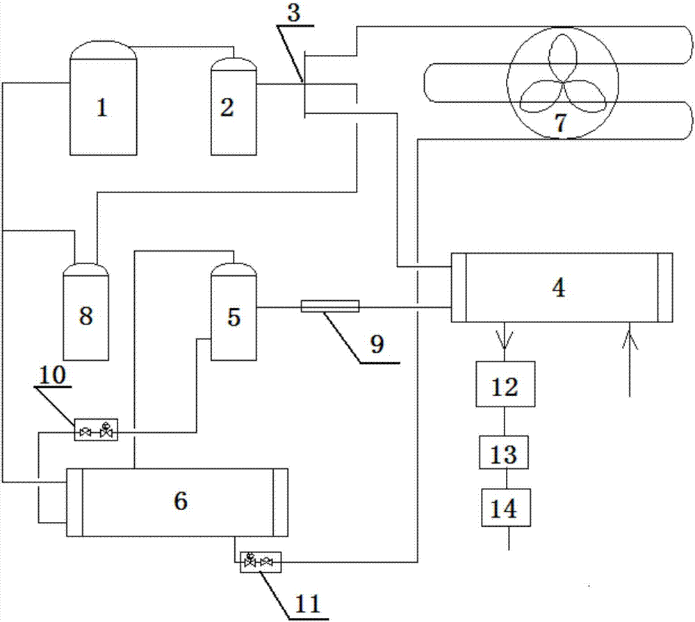
[0027] Such as figure 1 As shown, an air source heat pump heating system includes a compressor 1, an oil-gas separator 2, a four-way reversing valve 3, a water-cooled condenser 4, a separate liquid receiver 5, an evaporative condenser 6, and an air-cooled evaporator 7 and gas-liquid separator 8, the outlet of compressor 1 is connected to the inlet of oil-gas separator 2, and the four-way reversing valve 3 is respectively connected to the outlet of oil-gas separator 2, the working medium inlet of water-cooled condenser 4, and the gas-liquid separator 8 and the outlet of the air-cooled evaporator 7, the outlet of the working medium of the water-cooled condenser 4 is connected to the inlet of the separation reservoir 5 through a balance pipe 9, and the liquid phase outlet of the separation reservoir 5 passes through the first throttling assembly 1...


PUM


Abstract

The invention belongs to the technical field of energy and power engineering, and relates to an air source heat pump heating system. A four-way reversing valve is connected with an outlet of an oil-gas separator, a working medium inlet of a water cooling condenser, an inlet of a gas-liquid separator and an outlet of an air cooling evaporator; a working medium outlet of the water cooling condenseris connected with an inlet of a separation liquid storer through a balance pipe; a liquid-phase outlet of the separation liquid storer is connected with a first inlet of an evaporation condenser through a first throttling module; a gas phase outlet of the separation liquid storer is connected with a second inlet of the evaporation condenser; a first outlet of the evaporation condenser is connectedwith an inlet of a compressor; a second outlet of the evaporation condenser is connected with an inlet of the air cooling evaporator through a second throttling module; a hot water outlet of the water cooling condenser is connected with a water tank; the water tank is connected with a water pump; the water pump is connected with an auxiliary power supply; and the system adopts a mixed working medium consisting of R124 and R32. The system is high in energy-efficiency ratio, energy-saved, environment-friendly and wide in application range.

Description

technical field [0001] The invention belongs to the technical field of energy and power engineering, and in particular relates to a heat pump heating system, in particular to an air source heat pump heating system. Background technique [0002] 1. Current status of heating in residential quarters [0003] The existing winter heating of residential quarters is generally divided into: centralized heating of urban heating network, independent heating of residential quarters and independent heating of owners. According to the type of energy used, it is further divided into: coal-fired heating, gas heating, electric heating and Water source heat pump heating, etc. The use of air source heat pumps for heating has only just begun in recent years. In recent years, due to environmental protection considerations, some areas have gradually restricted heating methods such as coal and gas, and switched to cleaner electric heating and heat pump heating. [0004] 2. Disadvantages of cur...

Claims


Application Information

Patent Timeline
Patent Type & Authority Applications(China)
IPC IPC(8): F25B7/00F25B41/06F25B41/31
Inventor 焦景田
Owner 焦景田
Learn More