Pneumatic shot blast machine

A cleaning machine and shot blasting technology, applied in the field of machinery, can solve the problems of long conveying distance of conveyor belt, difficult to control, single, etc., and achieve the effect of high innovation, shortening conveying distance and improving practicability.

Pending Publication Date: 2018-01-16
QINGDAO ANTAI HEAVY IND MACHINERY
View PDF7 Cites 3 Cited by
  • Summary
  • Abstract
  • Description
  • Claims
  • Application Information

AI Technical Summary

Problems solved by technology

[0003] The shot blasting machine used for the engine block performs shot peening on the engine block, and different engine blocks generally have a specific shape, which requires the shot peening system of the shot blasting machine to handle objects with different regular shapes. Different surfaces have good shot blasting effect. The shot peening system in the existing shot peening machine for engine block is generally fixed. The shot peening system generally only performs shot blasting on a single square. The engine block Some locations in irregularly shaped objects such as
Moreover, the conveyor belt in the shot blasting machine is generally a parallel conveyor belt with a single support plate. The transmission distance of the conveyor belt is too long, which is difficult to control, and the conveyor belt with a single support plate is not easy to locate the engine block.

Method used


Image

  • Pneumatic shot blast machine
  • Pneumatic shot blast machine
  • Pneumatic shot blast machine

Examples


Embodiment Construction

[0031] The present invention is described in detail below in conjunction with accompanying drawing:

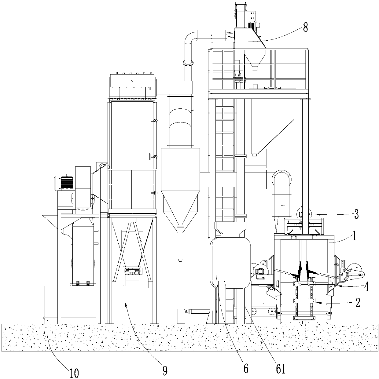
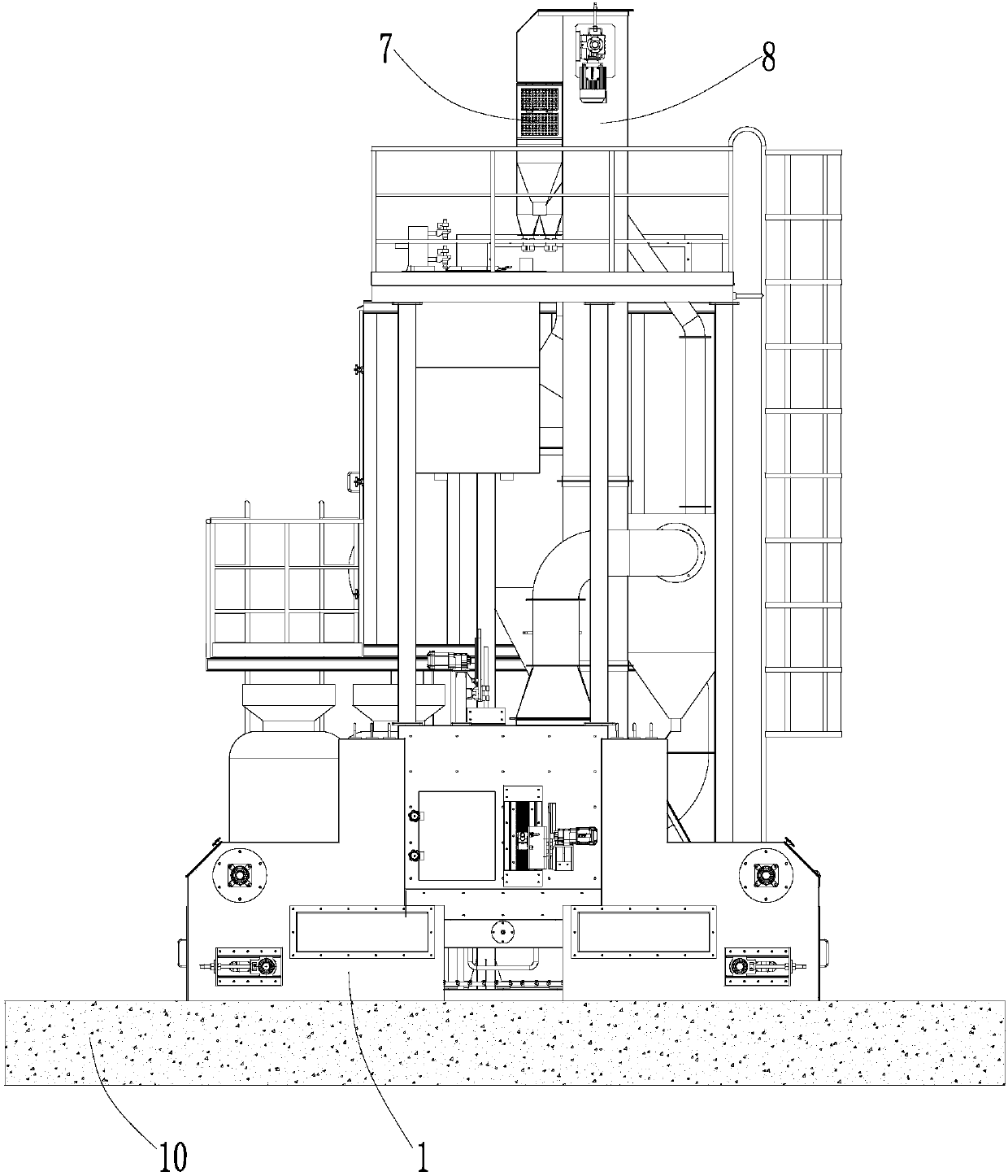
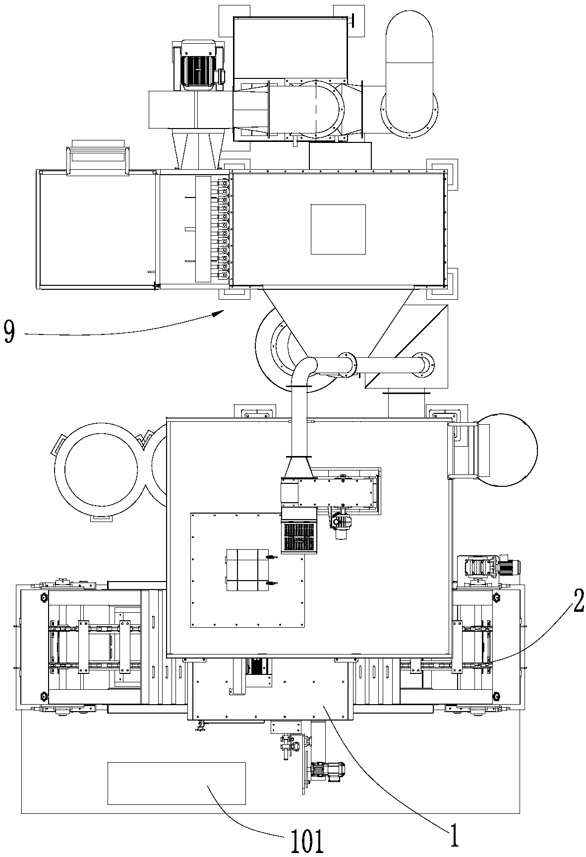
[0032] combine Figure 1 to Figure 9 , a shot blasting machine, comprising a shot blasting chamber 1, a shot blasting device and a conveying device 2, the conveying device 2 passes through the shot blasting chamber 1, and the shot blasting device includes an upper blasting device 3, a side blasting device 4 and a lower blasting device The shot blaster 5 and the side shot blaster 4 are divided into two groups: the left shot blaster and the right shot blaster, the upper shot blaster 3 is connected to the upper end of the shot blasting chamber 1, the side shot blaster 4 and the lower shot blaster 5 are all connected to the side end of shot blasting chamber 1.

[0033] Transmission device 2 comprises transmission support frame 21, transmission chain 22, reduction motor 23, belt seat bearing mechanism 24, slideway mechanism 25 and pallet mechanism 26, and transmission support fram...


PUM


Abstract

The invention discloses a pneumatic shot blast machine which comprises a shot-blast room, a shot-blast device and a conveying device, wherein the conveying device penetrates through the shot-blast room; the shot-blast device comprises an upper shot blast vessel, two groups of lateral shot blast vessels and a lower shot blast vessel, the upper shot blast vessel is connected to the upper end of theshot blast room, and the lateral shot blast vessels and the lower shot blast vessel are connected to the lateral end of the shot blast room; the upper shot blast vessel comprises an upper shot blast support, a first rotary disk, a first locating plate and a first shot blast pipe; each lateral shot blast vessel comprises a lateral shot blast support, a balance weight mechanism, a second rotary disk, a locating mechanism and a second shot blast pipe; the balance weight mechanism comprises a protection cover, a balance weight block arranged in a lower portion of the protection cover and a drivingwheel arranged in an upper portion of the protection cover; the lower shot blast vessel comprises a lower shot blast support, a third rotary disk, a third locating plate and a third shot blast pipe;a shot blast room rear notch is formed in a shot blast room lateral wall at the rear end of a shot blast room lateral notch. The pneumatic shot blast machine can perform better shot blast cleaning onirregular-shaped engine cylinder objects and has high creativity.

Description

technical field [0001] The invention relates to the field of machinery, in particular to a shot blasting machine. Background technique [0002] The shot blasting machine is different from the domestic sand blasting machine. Its process principle is to use the impact of the high-speed moving shot flow on the metal surface to generate a plastic cyclic strain layer on the surface, which leads to favorable changes in the microstructure of the layer and The residual compressive stress field is introduced into the surface layer. The microstructure of the surface layer and the residual compressive stress field are two strengthening factors to improve the fatigue fracture and stress corrosion (hydrogen embrittlement) fracture resistance of metal parts. As a result, the reliability and durability of the parts are improved. Sex is improved. Some important components in aircraft, locomotives, automobiles, steam turbines and other machinery, such as springs, shafts, gears, connecting r...

Claims


Application Information

Patent Timeline
Patent Type & Authority Applications(China)
IPC IPC(8): B24C3/14B24C9/00
Inventor 丁仁相王青峰刘延涛刘树强李洪磊
Owner QINGDAO ANTAI HEAVY IND MACHINERY
Why Eureka
Try Eureka