
Laser light-emitting device and preparation method thereof and laser illumination

A light-emitting device and laser technology, applied in the field of laser lighting, can solve problems such as the inability to use LD light sources, the easy burning of mixed fluorescent materials, and the need for research.

Inactive Publication Date: 2018-01-19
华芯半导体科技有限公司
View PDF5 Cites 0 Cited by
  • Summary
  • Abstract
  • Description
  • Claims
  • Application Information

AI Technical Summary

Problems solved by technology

Specifically, because the laser has a Gaussian distribution and the optical density of the laser is very high, this restricts the use of ordinary fluorescent materials in LD light sources, so LD light sources cannot use epoxy resin mixed fluorescent materials like LED light sources
Moreover, if the temperature of the laser light source is high, the mixed fluorescent material is easy to burn, and there are technical problems that affect the fluorescence excitation efficiency, so that the material to replace the epoxy resin needs to be resistant to high temperature and burning without affecting the fluorescence excitation efficiency. Function
[0004] Therefore, the mixed substrates doped with fluorescent materials that can be used in LD light sources at this stage remain to be studied.

Method used


Image

  • Laser light-emitting device and preparation method thereof and laser illumination
  • Laser light-emitting device and preparation method thereof and laser illumination
  • Laser light-emitting device and preparation method thereof and laser illumination

Examples


preparation example Construction

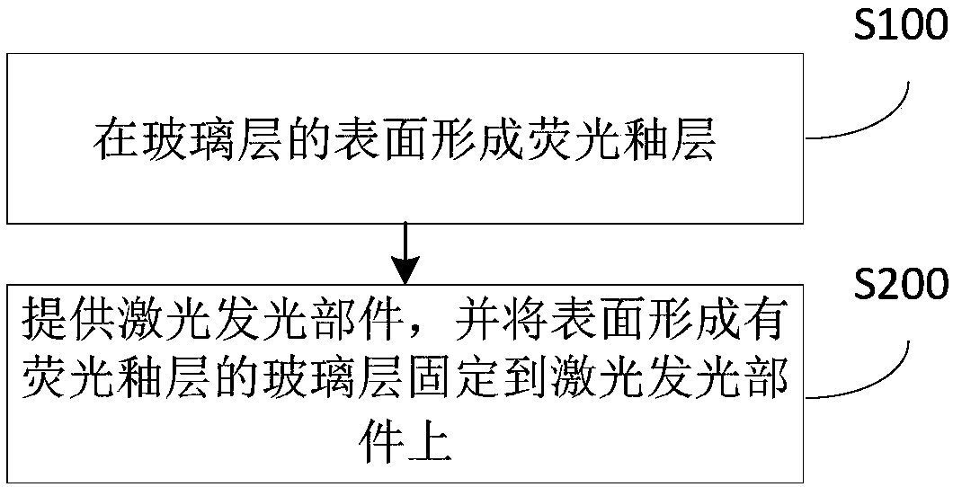
[0068] It should be noted that, in addition to step S100, the preparation method also includes other necessary steps, such as the preparation of the laser light-emitting component, the fixing of the glass layer and the laser light-emitting component, etc., and those skilled in the art can The specific structure is designed and supplemented. In some embodiments of the invention, reference figure 2 , the preparation method can further include:

[0069] S200: Provide a laser light-emitting component, and fix the glass layer with the fluorescent glaze layer formed on the surface to the laser light-emitting component.

[0070] In this step, a laser light-emitting component 100 is provided, and the glass layer 200 obtained in step S100 with the fluorescent glaze layer 300 formed on its surface is fixed to the laser light-emitting component 100, so as to obtain a laser light-emitting device.

[0071]According to the embodiment of the present invention, the specific method for prov...

Embodiment 1

[0078] In this embodiment, a fluorescent glaze layer on the surface of a glass layer in a laser light emitting device is prepared. Specifically, prepare according to the following steps:

[0079] 1. Evenly mix the low-temperature ceramic glaze, YAG fluorescent powder and water at a mass ratio of 1:1:2 to ensure that the mixed fluorescent glaze slurry has a certain fluidity as a whole. At the same time, wipe the surface of the glass layer 200 with alcohol to remove the surface stains. refer to Figure 5 , using a glue head to drip the uniformly mixed fluorescent glaze slurry 310 and drip it on the glass layer 200, until the fluorescent glaze slurry 320 evenly covers the entire surface of the glass layer 200;

[0080] 2. Put the glass layer 200 evenly distributed with the fluorescent glaze paste 320 in a high-temperature furnace for sintering treatment; and adopt the step-by-step heating method, first set the temperature to 60°C, keep it for 5 minutes after the temperature is ...

Embodiment 2

[0085] In this example, the fluorescent glaze layer on the surface of the glass layer in the laser light-emitting device was prepared according to the same method and conditions as in Example 1. The difference is that, in this example:

[0086] 1. Mix low-temperature ceramic glaze, YAG phosphor and water in a mass ratio of 2:1:2.

[0087] The fluorescent glaze layer formed on the surface of the glass layer of this embodiment can carry out X-ray diffraction analysis (XRD) to the fluorescent glaze layer, and the analysis result shows that the original crystal phase of the fluorescent powder is retained on the surface of the fluorescent glaze layer; The layer was subjected to spectral analysis, and the analysis results showed that the peak wavelength of the emission spectrum was 545nm, and the peak wavelength of the excitation spectrum was 450nm, indicating that the fluorescent glaze layer and the phosphor colloid had the same emission spectrum peak wavelength of 545nm. Therefor...


PUM

PropertyMeasurementUnit
Thicknessaaaaaaaaaa
Thicknessaaaaaaaaaa

Abstract

The invention provides a laser light-emitting device and a preparation method thereof and a laser illumination system of the laser light-emitting device. The laser light-emitting device comprises a laser light-emitting component; a glass layer and a fluorescent glaze layer, wherein the glass layer is arranged on a light-emitting face of the laser light-emitting component, and the fluorescent glazelayer is arranged on one side, far away from the laser light-emitting part, of the glass layer, and the fluorescent glaze layer is composed of ceramic glaze and yttrium aluminum garnet phosphor fluorescent powder. According to the laser light-emitting device, the fluorescent glaze layer is formed on the glass layer on the surface of the laser light-emitting component, and the fluorescent glaze layer is composed of the ceramic glaze and the yttrium aluminum garnet phosphor fluorescent powder; ceramic glaze with low expansion coefficient and high temperature resistance can effectively protectsyttrium aluminum garnet fluorescence powder which is evenly distributed in the fluorescent glaze layer, so that the fluorescent glaze layer can make the laser light-emitting device has high durability, high stability and efficiency.

Description

technical field [0001] The invention relates to the technical field of laser lighting, in particular, the invention relates to a laser light-emitting device, a preparation method thereof, and a laser lighting system. Background technique [0002] At this stage, with the rapid development of lighting technology, various lighting products emerge in an endless stream. At the same time, people's requirements for visual health and energy-saving and high-efficiency are also increasing day by day. People are no longer limited to dazzling lighting effects and low prices. Light-emitting diode (LED) lighting sources, which have the widest market coverage, are gradually being impacted by the market due to their disadvantages such as high blue light content, short luminous life, and low luminous efficiency. Therefore, with the increasing maturity of blue-light laser diode (LD) technology, its outstanding characteristics such as high efficiency of exciting fluorescent materials, high co...

Claims


Application Information

Patent Timeline
IPC IPC(8): F21K9/64F21V9/08F21Y115/30
Inventor 王智勇王志平刘友强郭丽敏王聪聪刘学胜谢文君
Owner 华芯半导体科技有限公司
Learn More