
Laser marking system based on computer control

A laser marking and computer technology, which is applied in the field of laser marking systems, can solve problems such as the lack of ability to process graphics files, achieve the effects of enriching interface control functions, improving control and processing speed, and reducing system wiring

Inactive Publication Date: 2018-01-19
ANHUI UNIVERSITY OF TECHNOLOGY AND SCIENCE
View PDF4 Cites 3 Cited by
  • Summary
  • Abstract
  • Description
  • Claims
  • Application Information

AI Technical Summary

Problems solved by technology

However, the existing single-chip controller can only complete several simple graphics (such as straight lines, arcs) marking, and lacks the ability to process graphics files.

Method used


Image

  • Laser marking system based on computer control
  • Laser marking system based on computer control
  • Laser marking system based on computer control

Examples


Embodiment

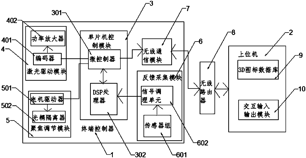
[0029] Such as figure 1 As shown, the present invention provides a computer-controlled laser marking system, including a terminal controller 1 and a host computer 2, the terminal controller 1 is installed on the laser, and the terminal controller 1 and the host computer 2 are connected via wireless channel for data transmission; the terminal controller 1 includes a single-chip control module 3, and the GPI O port of the single-chip control module 3 is connected with a laser driver module 4 and a focus adjustment module 5 through a cable, and the laser driver module 4 is connected to The driving end of laser, focus adjustment module 5 is connected to the adjustment end of focusing system; The SPI port of described single-chip microcomputer control module 3 is connected with feedback acquisition module 6, and described feedback acquisition module 6 is connected to laser and focusing mirror system, single-chip microcomputer control The communication port of module 3 is also conne...


PUM


Abstract

The invention discloses a laser marking system based on computer control. The system comprises a terminal controller and a host. The terminal controller comprises a single-chip microcomputer control module which is connected with a laser driving module and a focusing adjustment module. The laser driving module is connected to the driving end of a laser. The focusing adjustment module is connectedto the adjustment end of a focusing system. The SPI port of the single-chip microcomputer control module is connected with a feedback acquisition module. The feedback acquisition module is connected to the laser and a focusing mirror system. The communication port of the single-chip microcomputer control module is connected with a wireless communication module. The wireless communication module isused for carrying out data interaction with the host. The Ethernet port of the host is connected with a wireless router. The wireless router carries out data transmission with the wireless communication module. A 3D icon database and an interaction input and output module are arranged in the host. According to the invention, operation control of laser marking can be quickly achieved; carving of complex decorative patterns is achieved; and working efficiency is high and precision is high.

Description

technical field [0001] The invention relates to the field of laser marking systems, in particular to a computer-controlled laser marking system. Background technique [0002] Laser marking is a technology that uses the thermal effect of laser to ablate the surface material of the object to leave a permanent mark. Compared with traditional electrochemical and mechanical marking methods, it has the advantages of no pollution, high speed, high quality, great flexibility, and no contact with workpieces. It is suitable for industrial fields such as machinery, electronics, aerospace, light industry, food, and medicine. , can make all kinds of metal nameplates, etch specifications and models on tools, cutting tools, measuring tools and bearings. It has been widely used in European and American countries since the 1980s. At present, laser marking has replaced the traditional marking method in many fields and has become a conventional processing method, and even formed a new indust...

Claims


Application Information

Patent Timeline
Patent Type & Authority Applications(China)
IPC IPC(8): G05B19/042
Inventor 王军杨洋
Owner ANHUI UNIVERSITY OF TECHNOLOGY AND SCIENCE
Learn More