
Production apparatus of anethole rectifying section

A technology for production equipment and rectification section, which is applied in the production equipment field of anethole rectification section, can solve the problems of inability to accurately grasp the discharge time, affect anethole discharge, and affect the purity of anethole, so as to prevent air flow back Suction, reduce energy consumption, high production efficiency

Pending Publication Date: 2018-01-23
GUANGXI WANSHAN SPICE
View PDF1 Cites 2 Cited by
  • Summary
  • Abstract
  • Description
  • Claims
  • Application Information

AI Technical Summary

Problems solved by technology

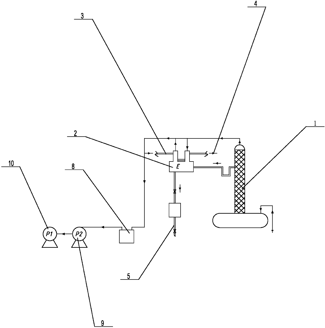
[0003] At present, the production plant structure of the anethole rectification section is as follows: figure 2 As shown, it includes a rectification tower, a condenser, a collection tank, and a vacuum extraction mechanism. The vacuum extraction mechanism vacuumizes the entire device, and then feeds the material to the rectification tower. After rectification, it enters the condenser to condense, and finally enters the collection tank for discharge. , this structural distillation has the following defects: the collection tank with a volume of 400L, the liquid level cannot be seen at the bottom 120L, and there is 30L of mixed liquid at the critical point of fraction separation, so the operator cannot accurately grasp the time of discharge, and the discharge time in advance The material affects the purity of anethole, and delaying the discharge wastes resources, and the volume of the collection tank is large, and the vacuum extraction requires a large energy consumption; energy, and the freezing point of anethole is 21.2°C, and the temperature drops in winter, so anethole is easy to freeze in the discharge pipe, which affects the discharge of anethole and reduces production efficiency

Method used


Image

  • Production apparatus of anethole rectifying section
  • Production apparatus of anethole rectifying section

Examples


Embodiment Construction

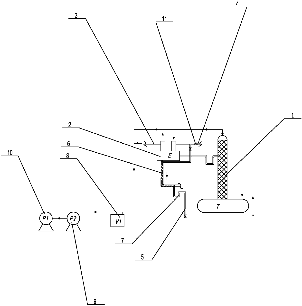
[0017] Such as figure 1 Propose a kind of specific embodiment of the present invention as shown, the production device of anethole rectification section, comprise rectification tower 1, the condenser 2 that is connected with rectification tower 1 successively by pipeline, extract vacuum mechanism, described vacuum mechanism comprises through The pipeline is connected to the vacuum buffer tank 8, Roots pump 9, and water ring pump 10 in sequence with the condenser 2. One side of the condenser 2 is connected to the condensed water inlet pipe 3, and the other side is connected to the condensed water outlet pipe 4. The bottom end of the condenser 2 is connected with a discharge pipe 5, the outer surface of the upper end of the discharge pipe 5 is covered with a condensed water insulation sleeve 6, and the bottom end of the discharge pipe 5 is provided with a discharge valve , the condensed water insulation sleeve 6 is connected to the condensed water outlet pipe 4, and the condens...


PUM


Abstract

The invention discloses a production apparatus of an anethole rectifying section. The production apparatus comprises a rectifying tower, and a condenser and a vacuumizing mechanism which are successively connected with the rectifying tower by virtue of a pipeline, wherein one side of the condenser is connected with a condensed water inlet pipe, the other side is connected with a condensed water outlet pipe, the bottom end of the condenser is connected with a discharging pipe, the outer surface of the upper end of the discharging pipe is coated with a condensed water heat-preserving casing pipe, and the condensed water heat-preserving casing pipe is connected with the condensed water outlet pipe. According to the production apparatus, the condenser is directly provided with the dischargingpipe, a collection tank of the existing structure is not needed, so that on one hand, the material can be precisely discharged, and the high purity of the anethole can be ensured, and on the other hand, the resource waste can be prevented, and the energy consumption is reduced; and the outer surface of the discharging pipe is also coated with the condensed water heat-preserving casing pipe, so that not only can the utilization rate of the energy be increased, but also the icing of the anethole can be prevented, the normal discharging of the apparatus is ensured, and the production efficiency is increased.

Description

technical field [0001] The invention relates to an anethole production equipment, in particular to a production device for the anethole rectification section. Background technique [0002] Fennel oil, that is, star anise oil, its main components are α-pinene, limonene, linalool, fennel, cis anethole, anisaldehyde, trans anethole, styrocene and cumin, among which anti The content of anethole is 83-91%, and that of fennel is 3-8%. Anethole is widely used in food, medicine, daily necessities, veterinary medicine, feed, pesticide and other fields. Anethole can also be used to produce products such as anisaldehyde, anisonitrile, anisitol, raspberry ketone, and ethestrol. The high-purity isolated product of fennel oil has wide application, high added value and good economic benefits. However, the high-purity isolated product of fennel oil cannot be achieved by simple separation techniques. In the production process of anethole, oil and water are generally separated first, then...

Claims


Application Information

Patent Timeline
IPC IPC(8): B01D3/14B01D3/32C07C41/40C07C43/215
Inventor 杨少凡万玉明马创伟雷长林邓意花
Owner GUANGXI WANSHAN SPICE
Learn More