Low-energy consumption reaction device

A reaction device and low energy consumption technology, applied in the field of low energy consumption reaction devices, can solve the problems of mechanical structure damage, high load of motor, power increase, etc., and achieve the effect of low cost, large power output and low energy loss

Inactive Publication Date: 2018-01-23
盐城市大丰匀力机械制造厂
View PDF0 Cites 4 Cited by
  • Summary
  • Abstract
  • Description
  • Claims
  • Application Information

AI Technical Summary

Problems solved by technology

However, as the speed of the stirring shaft increases, the power consumed also doubles. This method not only causes a high load on the motor, but also causes damage to the mechanical structure of the stirring shaft due to excessive resistance during stirring.

Method used


Image

  • Low-energy consumption reaction device
  • Low-energy consumption reaction device

Examples


Embodiment 1

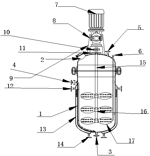
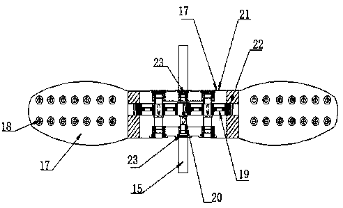
[0019] Embodiment 1: see Figure 1-Figure 2 , a low-energy reaction device, the low-energy reaction device includes a tank assembly, a power assembly, a heating assembly and a stirring assembly; the power assembly is installed above the tank assembly; the heating assembly is installed on the outer wall of the tank assembly ; The stirring assembly is installed inside the tank assembly, and the top is connected with the power assembly. The design structure is simple and clear, the components are closely connected and do not affect each other, the required parts are easy to replace, and it is easy to maintain the product during use in the future; the tank body components include tank body 1, manhole 2, outlet Liquid port 3, liquid inlet 4, pressure relief valve 5 and pressure outlet pipe 6; the manhole is installed on the left side of the top of the tank; the liquid inlet is located at the upper left side of the tank; the liquid outlet is located at the top of the tank The cente...


PUM


Abstract

The invention relates to a low-energy consumption reaction device. The low-energy consumption reaction device comprises a tank body assembly, a power assembly, a heating assembly and a stirring assembly; the power assembly is arranged above the tank body assembly; the heating assembly is arranged on the outer wall of the tank body assembly; the stirring assembly is arranged in the tank body assembly, and the top part is connected with the power assembly, the tank body assembly comprises a tank body, a manhole, a liquid outlet, a liquid inlet, a pressure release valve and a blow-off pipe; the manhole is arranged in the left side of the top part of the tank body; the liquid inlet is located in the top part of the left side of the tank body; the liquid outlet is located in the central position of the bottom part of the tank body. The low-energy consumption reaction device is characterized in that holes of particular shape are reserved in blades so that not only the contact area of the stirred material with the blades is reduced during stirring, but also the resistance of the blades is reduced when the blades rotate, when liquid flows through the holes at a high speed under the actionof the rotating force, the liquid entering from the holes forms a large swirl and can be ejected from the other end.

Description

technical field [0001] The invention relates to a reaction device with low energy consumption, which belongs to the technical field of chemical industry. Background technique [0002] The reactor is an important processing tool in industrial production. Through the structural design and parameter configuration of the reactor container, the heating, evaporation, cooling and low-speed mixing functions required by the process can be realized. Reactors are widely used in petroleum, chemical, rubber, pesticides, dyes, medicine, food and other fields. They are mainly used as pressure vessels for vulcanization, nitration, hydrogenation, alkylation, polymerization, condensation and other processes. When the reactor is stirring viscous objects, in order to improve the stirring effect, it will achieve a better mixing effect by increasing the rotation speed of the stirring shaft. However, as the speed of the stirring shaft increases, the power consumed also doubles. This method not on...

Claims


Application Information

Patent Timeline
Patent Type & Authority Applications(China)
IPC IPC(8): B01J19/18B01F7/30B01F15/00B01F15/06
Inventor 卞春梅陈云锦
Owner 盐城市大丰匀力机械制造厂
Why Eureka
Try Eureka