
Phase change cooling-based optical fiber cooling device for fiber laser

A fiber laser, phase change cooling technology, applied in the direction of laser cooling device, laser parts, structure/shape of active medium, etc., can solve the problems of inability to export, ineffective storage of heat, low heat capacity, etc., to improve high power tolerance ability, reducing the risk of sudden temperature changes, and ensuring reliability

Inactive Publication Date: 2018-01-23
CHINA WEAPON EQUIP RES INST
View PDF6 Cites 6 Cited by
  • Summary
  • Abstract
  • Description
  • Claims
  • Application Information

AI Technical Summary

Problems solved by technology

The disadvantage of this cooling device is that, limited by the inherent properties of thermally conductive silicone grease, its thermal conductivity is usually low, far lower than that of conventional metals, resulting in the inability to conduct the heat absorbed from the surface of the optical fiber in time, and its thermal capacity It is not high enough to effectively store too much heat, resulting in a relatively high overall thermal load of the system, which seriously restricts the development of fiber lasers to higher power

Method used


Image

  • Phase change cooling-based optical fiber cooling device for fiber laser
  • Phase change cooling-based optical fiber cooling device for fiber laser

Examples


Embodiment Construction

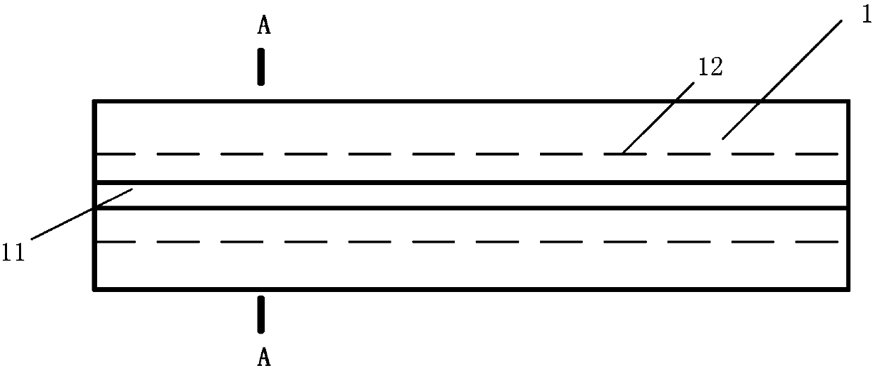
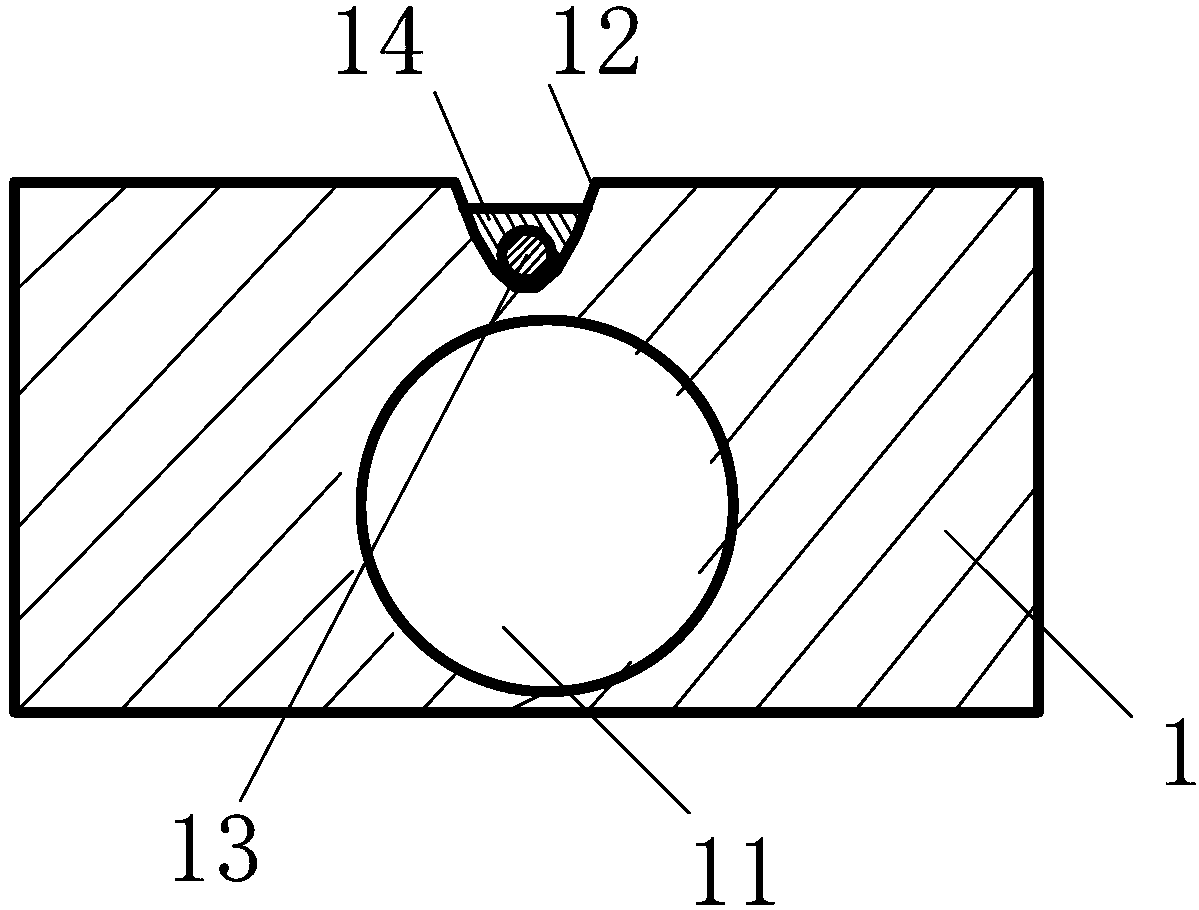
[0013] A fiber cooling device for a fiber laser based on phase change cooling, comprising a cooling heat sink 1, on which a fiber groove 12 is arranged, and a gain fiber 13 from which the coating layer has been removed is fixed in the fiber groove 12, wherein It is characterized in that the gain fiber 13 in the fiber groove 12 is filled with phase change material 14, and the phase change material 14 completely wraps the gain fiber 13 in the fiber groove 12 in the middle; there is a cooling water channel 11 in the cooling heat sink 1, cooling The water channel 11 is below the fiber groove 12 .

[0014] The phase change material 14 is a composite material composed of paraffin wax and graphite in any proportion, or an organic material with phase change properties of fully refined paraffin wax, myristyl alcohol, and stearic acid, or composed of stearic acid and metal powder in any proportion of composite materials.

[0015] The cross-section of the cooling water channel 11 of the...


PUM


Abstract

The invention relates to a phase change cooling-based optical fiber cooling device for a fiber laser. The device comprises a cooling heat sink (1). An optical fiber groove (12) is arranged on the cooling heat sink (1). A gain optical fiber (13) of which the coating layer is removed is fixed in the optical fiber groove (12). The device is characterized in that the a phase change material (14) fillsaround the gain optical fiber (13) in the optical fiber groove (12) and completely wraps the gain optical fiber (13) in the optical fiber groove (12); a cooling water channel (11) is arranged insidethe cooling heat sink (1); and the cooling water channel (11) is located below the optical fiber groove (12). In addition to the functions of a conventional fiber optic cooling heat sink, the phase change cooling-based optical fiber cooling device of the invention has the functions of preventing sudden temperature change and enduring higher power. With the device adopted, the capability of a fiberlaser system to withstand high-power can be increased, the risks of sudden temperature change can be reduced, and the reliability of the system can be ensured.

Description

technical field [0001] The invention relates to an optical fiber cooling device for an optical fiber laser based on phase change cooling, which belongs to the field of lasers, and in particular relates to the technical field of optical fiber cooling in optical fiber laser technology. Background technique [0002] High-power fiber lasers have the advantages of high conversion efficiency, good beam quality, convenient thermal management, and compact structure, and are widely used in industrial processing, cutting, marking, welding and other fields. High-power fiber lasers rely on electrical energy to produce a high-brightness, focused laser beam, but generate a lot of heat in the process. Although the fiber laser has a large surface area and volume ratio, it can effectively dissipate heat at low power, but with the continuous increase of pump power, especially for Yb-doped 3+ For double-clad fiber lasers, if the temperature of the doped fiber increases, the number of thermal ...

Claims


Application Information

Patent Timeline
IPC IPC(8): H01S3/04H01S3/067
Inventor 董超孙伟谷亮张红杨宁
Owner CHINA WEAPON EQUIP RES INST
Learn More