
Three-dimensional scanning laser radar based on MEMS micromirror

A technology of three-dimensional scanning and laser radar, which is applied in the field of laser detection, can solve problems such as restricting the development of multi-line laser radar, limited characteristic information of the object to be measured, and increased vertical volume, and achieves convenient installation and adjustment, reduced emission diodes, and power Effect of heat dissipation reduction

Pending Publication Date: 2018-01-30
北京因泰立科技有限公司
View PDF11 Cites 25 Cited by
  • Summary
  • Abstract
  • Description
  • Claims
  • Application Information

AI Technical Summary

Problems solved by technology

Two-dimensional scanning lidar is mostly single-line scanning, which rotates 360° in the horizontal direction, and the scanning surface is a horizontal plane, so the characteristic information of the object to be measured is very limited.
[0003] The current 3D scanning lidar mostly adopts multi-line scanning mode, that is, multiple laser tubes are used to emit sequentially, and the structure is that multiple laser tubes are arranged vertically. There is a certain angle between each laser tube, and the vertical emission field of view is within 30°. -40°, the receiving module receives at the corresponding angle, and each receiving detector corresponds to a transmitting angle. The structure is that the receiving module and the transmitting module are arranged symmetrically on both sides, and multiple mirrors are used to turn the optical path, and then in the horizontal direction Rotation realizes three-dimensional scanning and ranging. This multi-line radar uses multiple launch tubes. Each launch tube needs to be collimated and the launch angle must be adjusted, and multiple internal mirrors must be adjusted to turn the optical path. The installation and adjustment is complicated, although it has been mass-produced , but due to the large number of emitting diodes, the process is complicated and the cost remains high
[0004] In order to meet the requirements, it is necessary to quickly obtain scanning test information, and collect more characteristic information to improve dot matrix pixels. The multi-line laser radar uses the control of multiple emitting diodes to emit sequentially in the vertical direction. In order to improve the scanning resolution in the vertical direction, the diodes in the vertical direction The number must be increased. At present, the maximum number of lines is 64 lines. Therefore, the volume in the vertical direction increases, and the power consumption and heat dissipation increase, which restricts the development of multi-line lidar.
Another 3D scanning laser radar uses phased array to control the emission angle, but its maximum test angle in the horizontal direction is 120°, and multiple laser radars need to be used together to achieve 360° circular scanning

Method used


Image

  • Three-dimensional scanning laser radar based on MEMS micromirror
  • Three-dimensional scanning laser radar based on MEMS micromirror
  • Three-dimensional scanning laser radar based on MEMS micromirror

Examples


Embodiment Construction

[0032] In order for those skilled in the art to better understand the technical solution of the present invention, a MEMS micromirror-based three-dimensional scanning laser radar provided by the present invention will be described in detail below with reference to the accompanying drawings.

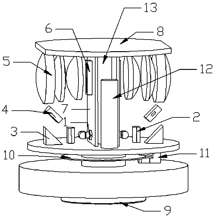
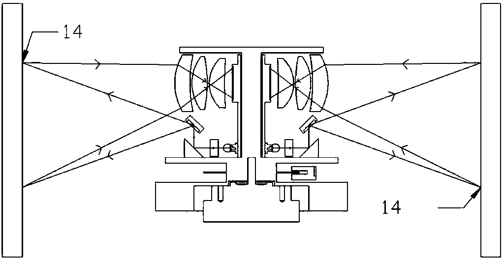
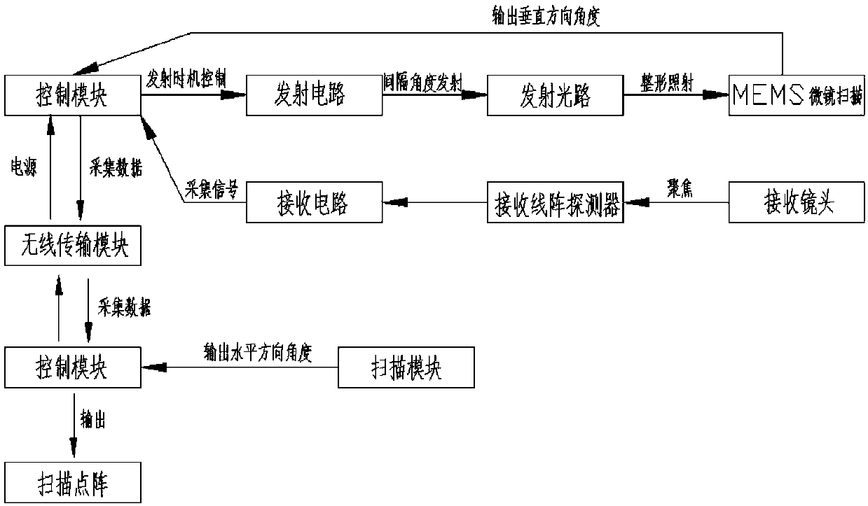
[0033] A three-dimensional scanning laser radar based on a MEMS micromirror, including: a transmitting module, which is used to scan and emit laser light in the vertical direction, and output the vertical direction emission angle; a receiving module, which is used to receive the echo signal reflected by the object to be measured; The module is connected with the transmitting module and the receiving module, and is used to provide high voltage for the transmitting module and the receiving module; the counterweight module is used for the counterweight of the entire rotating body to achieve dynamic balance; the scanning module rotates and scans in the horizontal direction, and outputs the hori...


PUM


Abstract

The invention provides a three-dimensional scanning laser radar based on an MEMS micromirror. The three-dimensional scanning laser radar comprises an emitting module, a receiving module, a high-voltage module, a counterweight module, a scanning module, a control module and a wireless transmitting module, wherein the emitting module is used for scanning and emitting in a vertical direction; the receiving module is used for receiving an echo signal reflected by an object to be detected; the high-voltage module is used for providing high voltages for transmission and reception; the counterweightmodule is used for dynamically balancing an entire rotating body; the scanning module is used for rotationally scanning in a horizontal direction and outputting an angle; the control module is used for controlling the whole machine and running an algorithm; the wireless transmitting module is used for wireless power supply and data transmission. The three-dimensional scanning laser radar adopts asingle laser diode as the emitting module to irradiate the MEMS micromirror and scan in the vertical direction, the receiving module performs reception in the vertical direction, the emitting module and the receiving module are integrated, and the scanning module rotates at 360 degrees in the horizontal direction to realize three-dimensional scanning. The three-dimensional scanning laser radar based on the MEMS micromirror provided by the invention has the advantages of compact structure, dense dot matrix pixels, and convenient assembly and adjustment.

Description

technical field [0001] The invention belongs to the technical field of laser detection, in particular to a three-dimensional scanning laser radar based on a MEMS micromirror. Background technique [0002] Laser scanning ranging radar can be used to detect the position, contour and speed of the target. The application field of laser ranging radar is gradually expanding, accurate measurement, navigation and positioning, safe obstacle avoidance, and it has begun to be applied to unmanned driving technology. Laser scanning radar The emitted laser beam is rotated and scanned to form a scanning section, so as to test the characteristic information of the object to be measured. At present, laser scanning radar includes two-dimensional scanning laser radar and three-dimensional scanning laser radar. Most of the two-dimensional scanning lidar is a single-line scanning, which rotates 360° in the horizontal direction, and the scanning surface is a horizontal plane, so the characterist...

Claims


Application Information

Patent Timeline
Patent Type & Authority Applications(China)
IPC IPC(8): G01S7/481
Inventor 高东峰王剑波王鹏王春生
Owner 北京因泰立科技有限公司
Learn More