
High power microwave radial line mode conversion slot antenna

A high-power microwave and mode-converting technology, applied in the field of radiation antennas, can solve the problems of high-frequency application difficulties, limited power capacity, and low compactness of high-power microwave antennas.

Active Publication Date: 2018-01-30
NAT UNIV OF DEFENSE TECH
View PDF6 Cites 4 Cited by
  • Summary
  • Abstract
  • Description
  • Claims
  • Application Information

AI Technical Summary

Problems solved by technology

[0006] The technical problem to be solved by the present invention is to provide a new type of high-power microwave radial line mode conversion slot antenna, which has a compact structure, coaxial input and output, and high power capacity and gain. The degree of modernization is not high, the power capacity is limited, and it is difficult to apply in high frequency bands.

Method used

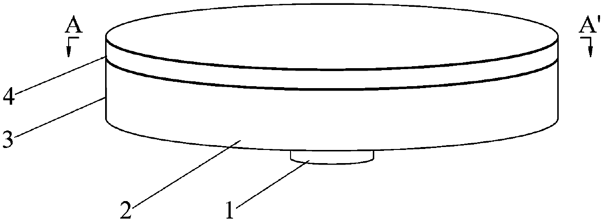
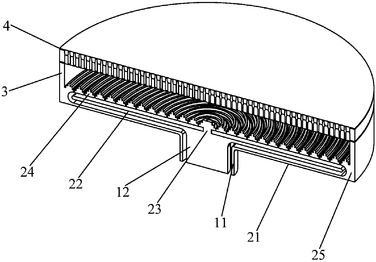
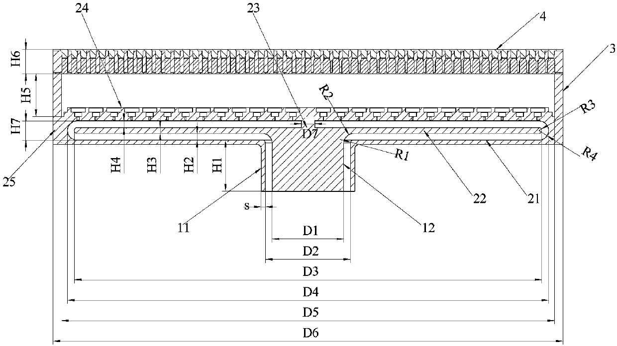

Image

  • High power microwave radial line mode conversion slot antenna
  • High power microwave radial line mode conversion slot antenna
  • High power microwave radial line mode conversion slot antenna

Examples


Embodiment 1

[0051] Provide N=10 below, be used for 12GHz (being that the frequency of input microwave source is 12GHz, corresponding microwave wavelength is 25mm) the concrete design dimension of an embodiment of the high-power microwave continuous transverse stub slot radial line antenna:

[0052] At this frequency, the diameter D1 of the inner conductor 11 of the coaxial waveguide 1 and the inner diameter D2 of the outer conductor 12 should satisfy According to actual needs, select D1=100mm, D2=119mm, the length of outer conductor 12 H1=60mm, and the length of inner conductor H1+H2=60+9.5=69.5mm; choose radial line leaky waveguide 2 waveguide wall 25 according to actual needs The outer diameter D6=560mm, under the premise that the microwave is transmitted without loss in the radial line leaky waveguide 2, the simulation optimization obtains the chamfer radius R1=3.9mm at the connection between the outer conductor 11 and the radial line bottom plate 21, The radius of the chamfer at the ...

Embodiment 2

[0058] Provide N=13 below, be used for 14.2GHz (being that the frequency of input microwave source is 14.2GHz, corresponding microwave wavelength is 21.03mm) the specific design dimension of an embodiment of the high-power microwave continuous transverse stub slot radial line antenna:

[0059] At this frequency, the diameter D1 of the inner conductor 11 of the coaxial waveguide 1=84mm, the inner diameter D2=100mm of the outer conductor 12, the length H1=60mm of the outer conductor 12, and the length of the inner conductor is H1+H2=60+8= 68 mm; the outer diameter D6 of the waveguide wall 25 of the radial line leaky waveguide 2 = 600 mm, the chamfer radius R1 of the connection between the outer conductor 11 and the radial line bottom plate 21 = 3.28 mm, the inner conductor 12 is connected with the radial line middle plate 22 Chamfer radius R2 = 12.01mm; inner diameter D4 of waveguide wall 25 of radial line leaky waveguide 2 = 572.5mm, radius of fillet inside waveguide wall R4 = 1...

Embodiment 3

[0065] Provide N=17 below, be used for 18GHz (being that the frequency of input microwave source is 18GHz, corresponding microwave wavelength is 16.7mm) the specific design dimension of an embodiment of the high-power microwave continuous lateral stub slot radial line antenna:

[0066] At this frequency, the diameter D1 of the inner conductor 11 of the coaxial waveguide 1 = 66.7mm, the inner diameter D2 of the outer conductor 12 = 79.3mm, the length H1 of the outer conductor 12 = 60mm, and the length of the inner conductor is H1+H2=60+ 6.3 = 66.3mm; the outer diameter D6 of the waveguide wall 25 of the radial line leaky waveguide 2 = 600mm, the chamfer radius R1 of the connection between the outer conductor 11 and the radial line bottom plate 21 = 2.6mm, the inner conductor 12 and the radial line center The chamfer radius R2 at the joint of the plates 22 is 9.5 mm; the inner diameter of the waveguide wall 25 of the radial line leaky waveguide 2 is D4 = 589.5 mm, and the radius ...


PUM


Abstract

The invention discloses a high power microwave radial line mode conversion slot antenna. The problems of being loose, limited power capacity and the like of a high power microwave antenna are solved.The antenna provided by the invention consists of a coaxial waveguide, a radial line leaky waveguide, a flange plate and a mode conversion lens. The radial line leaky waveguide is composed of a radialline bottom plate, a radial line middle plate, a short circuit cylinder, a slot array actinal surface and a waveguide wall. The slots of the slot array actinal surface are capsule-shaped slots whichare uniformly arranged in the circumferential direction. An annular protrusion step is added between adjacent slots to form a radiation branch. The mode conversion lens is composed of a first matchinglayer, a metal disc, a filling medium and a second matching layer. The metal disc is formed by combining mode conversion units arranged in the shape of a honeycomb. The mode conversion units are formed by punching inside a prismoid. According to the invention, the high power microwave radial line mode conversion slot antenna has the advantages of compact structure and high power capacity and gain; and the problem that the high power microwave antenna has limited power capacity and is difficultly used in a high frequency band is solved.

Description

technical field [0001] The invention relates to a radiation antenna in the technical field of high-power microwaves, in particular to a high-power microwave mode conversion antenna working in a high-frequency band. Background technique [0002] High-power microwave (High-Power-Microwave, abbreviated as HPM) generally refers to strong electromagnetic radiation with a frequency between 300 MHz and 300 GHz and a peak power greater than 100 MW or an average power greater than 1 MW. There are various applications of high-power microwaves, mainly including: high-power pulse radar, which is used to accurately distinguish targets in a wide frequency band; high-energy particle radio-frequency accelerators, which are used in high-energy physics and nuclear physics research; Plasma heating and high-power microwave weapons and other fields. [0003] So far, the research results of high-power microwave sources are mainly concentrated in the L, S, C, X and other bands (the frequencies ar...

Claims


Application Information

Patent Timeline
Patent Type & Authority Applications(China)
IPC IPC(8): H01Q1/50H01Q13/10H01Q15/02H01Q15/24H01Q19/06
Inventor 袁成卫孙云飞贺军涛张强张晓萍冯加怀李志强党方超
Owner NAT UNIV OF DEFENSE TECH
Learn More