Decoupling control method of PWM rectifier having capacitive load

A capacitive load, decoupling control technology, applied in the output power conversion device, the conversion of AC power input to DC power output, electrical components and other directions, can solve the problems of low accuracy, easy system instability, etc., to achieve control The strategy is simple, the mathematical model is simplified, and the effect is easy to achieve

Inactive Publication Date: 2018-01-30
由国峰
View PDF0 Cites 1 Cited by
  • Summary
  • Abstract
  • Description
  • Claims
  • Application Information

AI Technical Summary

Problems solved by technology

The nonlinear control strategy of the current source rectifier can achieve satisfactory steady-state and transient characteristics, but the disadvantage is that the accuracy of linearization is not high under light-load conditions, and the system is prone to instability

Method used


Image

  • Decoupling control method of PWM rectifier having capacitive load
  • Decoupling control method of PWM rectifier having capacitive load
  • Decoupling control method of PWM rectifier having capacitive load

Examples


Embodiment Construction

[0017] specific implementation plan

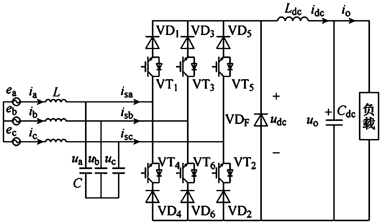
[0018] figure 1 In , considering the diversity of the load, the load current i can be regarded as a disturbance, and the CSR main circuit with capacitive load is obtained. The anti-parallel diode VDF on the DC side is used for freewheeling when the three-phase bridge arm is in 0 state, and the bus capacitance is . figure 1 The coupled inductor in the analysis can be used as a single inductor Equivalent, its inductance is equal to the total inductance of the coupled inductor when the coupling coefficient is 0.95. The equivalent dq rotation transformation is performed on the voltage, current and switching functions in the figure, and the dq side equation and the ac side equation under the dq rotation coordinate system can be obtained.

[0019]

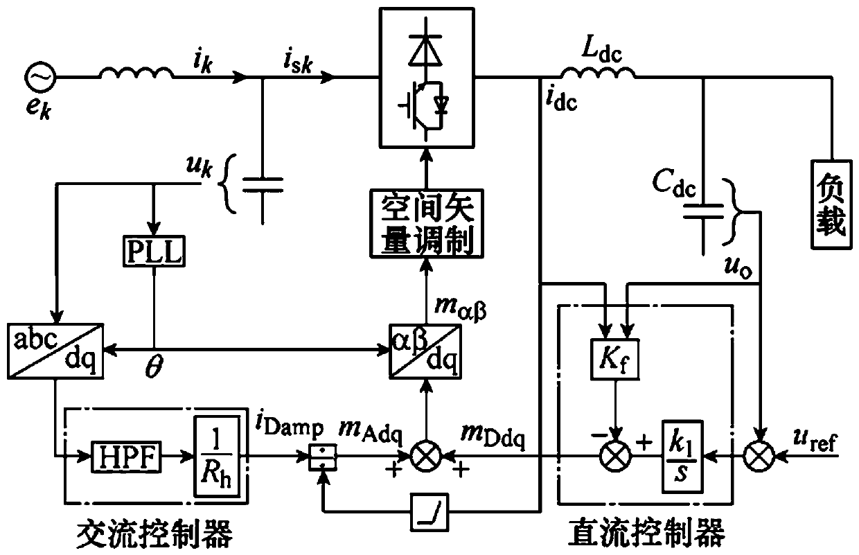
[0020] figure 2 In , the CSR overall control block diagram consists of two parts: the state feedback controller on the DC side and the virtual impedance controller on the AC side. are t...


PUM


Abstract

The invention discloses a decoupling control method of PWM rectifier having capacitive load. A mathematical model of a rotating coordinate is established for a capacitive load PWM type CSR. Through orienting d axis to AC filtering capacitance voltage vector, the mathematical model can be simplified as a DC side model and an AC side model, which are in mutual decoupling, and further speaking, the independent control of the DC side and the AC side can be realized. The invention is advantageous in that the state feedback control is adopted at the DC side to stabilize DC bus voltage, and virtual impedance is introduced at the AC side to carry out a control method of grid side current active damping; the mutual influence between the DC side and the AC side due to the PWM modulation process canbe eliminated, and the decoupling control between the DC side and the AC side can be realized.

Description

Technical field [0001] The invention relates to a PWM rectifier, in particular to a decoupling control method for a PWM rectifier with a capacitive load. Background technique [0002] It is an inevitable trend to adopt PWM rectifier in Uninterruptible Power Supply (UPS). In the PWM rectifier, compared with the voltage source rectifier (Voltage Source Rectifier, VSR), the current source rectifier (Current Source Rectifier, CSR) can work at a lower DC bus voltage, the grid side does not need a step-down transformer, and is easy to parallel operation and has built-in short-circuit protection. These advantages make CSR have great application prospects in UPS. However, when CSR is applied to UPS, the DC side needs to control both DC voltage and DC current, and the large capacitance at the DC output end increases the order of the mathematical model, which brings great challenges to the design of the controller. difficulty. [0003] The conventional CSR DC side only has large i...

Claims


Application Information

Patent Timeline
Patent Type & Authority Applications(China)
IPC IPC(8): H02M7/219
Inventor 由国峰
Owner 由国峰
Why Eureka
Try Eureka