Pressurizing disc filter discharging device

A disc filter and discharger technology, applied in the direction of filtration separation, mobile filter element filter, separation method, etc., can solve the problems of increasing equipment and civil construction investment, large discharge height, filter product clogging, etc. It achieves the effect of reducing equipment and civil construction investment, reducing the height occupied by nesting, and reducing the failure rate

Active Publication Date: 2018-02-02
MCC NORTH (DALIAN) ENG TECH CO LTD
View PDF4 Cites 1 Cited by
  • Summary
  • Abstract
  • Description
  • Claims
  • Application Information

AI Technical Summary

Problems solved by technology

This discharge method is intermittent discharge, and the wet and fine-grained filter products are easy to block in the collection hopper and discharge hopper
The height occupied by the nesting is large, which increases the investment in equipment and civil engineering, and increases the failure rate

Method used


Image

  • Pressurizing disc filter discharging device

Examples


Embodiment Construction

[0018] The specific implementation manner of the present invention will be further described below in conjunction with the accompanying drawings.

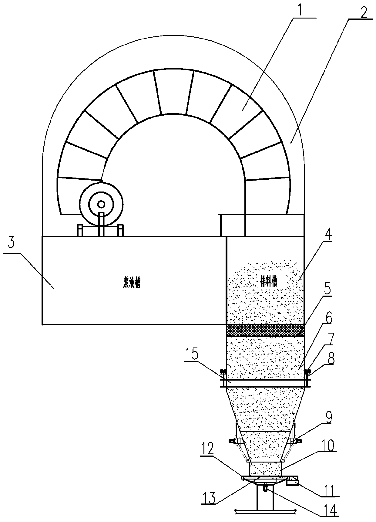
[0019] Such as figure 1 As shown, a discharge device for a pressurized disc filter of the present invention includes at least one circular filter disc 1, a slurry tank 3, and a discharge tank 4 fixed on the main shaft arranged along the axial direction of the main shaft, for The scraper device for unloading, the pressurization system 2 and the discharge system are characterized in that:

[0020] The discharge system is composed of a lower sealed silo 6 and a discharge machine 12 for storing filtered products and sealing the compressed air;

[0021] The lower sealed silo 6 is located below the discharge tank 4 of the filter. It has a large upper opening and a smaller lower opening. The upper opening is a square feeding opening and the lower opening is a circular discharge opening. The four sides are sealed and the bottom is open. ...


PUM


Abstract

The invention relates to a pressurizing disc filter discharging device which comprises a circular filter disc, a grout groove, a discharging groove, a scraper device for discharging, a pressurizing system and a discharging system. The device is characterized in that the discharging system is composed of a lower sealing material bin and a discharger, wherein the lower sealing material bin is used for stacking filter products and achieving the material layer sealing effect on compressed air; the discharger is located below a circular discharging outlet in the lower sealing material bin, a cylindrical feeding hopper is arranged at the upper portion of the discharger, an upper opening of the cylindrical feeding hopper is in bolt connection with the circular discharging outlet in the lower sealing material bin, a set of rotatable impellers annularly arranged at equal angles are arranged inside the discharger, an impeller shaft is connected with a frequency conversion motor of the discharger, the discharging outlet is formed in one side of the discharger, and a pressure gauge and the frequency conversion motor of the discharger are interlocked. The device has the advantages of being simple in structure, small in occupied space, small in occupied height difference, low in equipment and civil engineering investment, low in fault rate and capable of achieving continuous discharging andpreventing material blockage.

Description

technical field [0001] The invention belongs to the technical field of solid material dehydration, and in particular relates to a discharge device of a pressurized disc filter. Background technique [0002] The disc filter is widely used in the dehydration of solid powder due to its continuous operation, large processing capacity per unit area, small footprint, and low cost. Most of the current disc filters are vacuum disc filters, which rely on vacuuming to achieve dehydration. However, since the ultimate vacuum of vacuuming is an atmospheric pressure (about 0.1Mpa), the moisture filtered by it is generally high, and the moisture content of general products Between 10% and 20%, and many filtration processes now have very low moisture requirements for filtered products, and traditional vacuum disc filters cannot meet the requirements. At present, there is a pressurized disc filter, which can be filtered with positive pressure of compressed air, and the filtered water can be...

Claims


Application Information

Patent Timeline
Patent Type & Authority Applications(China)
IPC IPC(8): B01D33/76B01D33/80B01D33/17
CPCB01D33/17B01D33/76B01D33/80B01D33/808Y02P70/10
Inventor 李国洲
Owner MCC NORTH (DALIAN) ENG TECH CO LTD
Why Eureka
Try Eureka