Large-flow engine oil pump of internal combustion

A technology of internal combustion engine and oil pump, which is applied to machines/engines, liquid fuel engines, pumps, etc., can solve the problems of reduced performance and service life, small volume ratio, rapid oil quality decline, etc., to reduce user maintenance costs, lubrication The effect of function enhancement and production cost reduction

Inactive Publication Date: 2018-02-02
王友宏
View PDF5 Cites 0 Cited by
  • Summary
  • Abstract
  • Description
  • Claims
  • Application Information

AI Technical Summary

Problems solved by technology

During the speed change process of the internal combustion engine, the oil supply and pressure of the oil pump will change with the change of the speed, resulting in some unstable factors, usually unstable oil supply, cavitation, large oil pressure fluctuations, and oil loss Large, even oil pump overload damage and other adverse phenomena (especially single-cylinder engine is more prominent), due to the matching design of the traditional oil pump and the main engine, in order to ensure that all parts of the main engine can be fully lubricated, the set flow and pressure are higher than the main engine. Therefore, when the speed of the main engine is increased to a certain range, the oil pump is generally overloaded, resulting in vicious wear of the oil pump overload, increased power consumption, reduced performance and service life. Abnormal injection causes bubbles in the circuit oil, and the circulating oil is prone to cavitation, and the oil circulation frequency is too high, resulting in rapid decline in oil quality and high fuel consumption
[0003] At present, the internal combustion engine oil pump in the prior art has a small rotor cavity space and a small volume ratio, resulting in a small flow rate. During the acceleration process of the main engine of the internal combustion engine, due to the sudden increase in the rotational speed, the oil flow rate cannot keep up with the requirements required for the increased rotational speed. , can not get the best effect of lubrication

Method used


Image

  • Large-flow engine oil pump of internal combustion
  • Large-flow engine oil pump of internal combustion
  • Large-flow engine oil pump of internal combustion

Examples


Embodiment

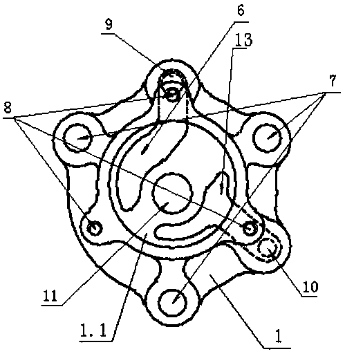
[0028] In this embodiment, the model is S1110 oil pump as an example, such as figure 1 , 2 Shown:

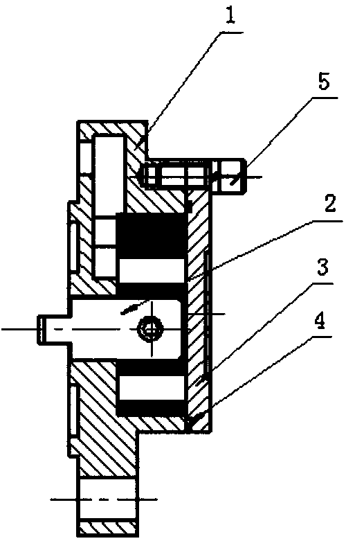
[0029] The S1110 engine oil pump in this embodiment includes a pump body 1 , a rotor assembly 2 , a pump cover 3 and a seal 4 .

[0030] The pump body 1 is connected to the pump cover 3, and a rotor cavity is formed between the pump body 1 and the pump cover 3; the rotor assembly 2 is located in the aforementioned rotor cavity; the seal 4 is arranged at the joint between the pump cover 3 and the pump body 1 .

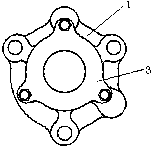
[0031] Such as image 3 shown. The cross section of the pump body 1 is in the shape of an irregular arc. Pump body 1HT250 casting; the outer peripheral wall of pump body 1 is provided with oil inlet hole 9, oil outlet hole 10, oil pump installation screw hole 7 and pump cover installation screw hole 8; pump body 1 is provided with a concave stepped cavity 1.1; the wall thickness of the concave stepped cavity 1.1 on the pump body 1 is 23mm; the concave stepped cavity...


PUM


Abstract

The invention discloses a large-flow oil pump of an internal combustion engine. The large-flow oil pump solves the technical problem that in the prior art, a rotor cavity of the oil pump of an original internal combustion engine is small in space and the volume fraction is not large so that the flow is small, in the acceleration process of a main engine of the internal combustion engine, the engine oil flow cannot meet the requirement of the increasing of rotating speed because the rotating speed is increased suddenly so that the lubricating optimal effect cannot be achieved. According to thetechnical scheme, the large-flow oil pump of the internal combustion engine comprises a pump body, a rotor assembly and a pump cover; the section of the pump body is in an irregular arc shape; the pump body adopts an HT250 casting; oil inlet holes, oil outlet holes, an oil pump mounting screw hole and a pump cover mounting screw hole are formed in the outer peripheral wall of the pump body; the pump body is provided with an inward-concave step cavity; the pump cover is in a plate shape; the pump cover and the pump body are in interference fit; a pump cover mounting hole corresponding to the pump cover mounting screw hole in the pump body is formed in the outer peripheral wall of the pump cover; one side face of the pump cover is an inner mounting surface; and the inner mounting surface isprovided with an outer convex column corresponding to a positioning bulge on an inner rotor.

Description

technical field [0001] The invention relates to a large-flow internal combustion engine oil pump. Background technique [0002] With the wide application of internal combustion engines in many fields, their speed-up and shifting ranges have been greatly expanded, that is, their performance and quality have been greatly improved. Therefore, modern internal combustion engines put forward higher requirements on the performance of the oil pump, the main component of the lubrication system. At present, the internal meshing cycloidal rotor oil pump is generally used in small and medium-sized internal combustion engines in my country. During the speed change process of the internal combustion engine, the oil supply and pressure of the oil pump will change with the change of the speed, resulting in some unstable factors, usually unstable oil supply, cavitation, large oil pressure fluctuations, and oil loss Large, even oil pump overload damage and other adverse phenomena (especially...

Claims


Application Information

Patent Timeline
Patent Type & Authority Applications(China)
IPC IPC(8): F16N13/20F04C2/10F04C15/00
CPCF16N13/20F04C2/082F04C2/10F04C15/00F04C15/0003
Inventor 王友宏朱巧君
Owner 王友宏
Why Eureka
Try Eureka