
Thermoelectric generation module based on flat plate heat pipes and heat pipe circulation waste heat thermoelectric generation system formed by thermoelectric generation module based on flat plate heat pipes

A thermoelectric power generation module and technology of thermoelectric power generation, applied in the direction of generators/motors, electrical components, etc., can solve problems such as difficult large-scale power generation applications, large influence of pipeline systems, and small heat transfer of heat pipes, etc., to achieve flexible design and installation, reduce The effect of high product price and heat transfer efficiency

Pending Publication Date: 2018-02-02
NANJING UNIV OF AERONAUTICS & ASTRONAUTICS
View PDF2 Cites 10 Cited by
  • Summary
  • Abstract
  • Description
  • Claims
  • Application Information

AI Technical Summary

Problems solved by technology

A thermoelectric power generation heat pipe and a thermoelectric power generation device (application number 200810220647.X) and a waste heat utilization thermoelectric power generation pipeline device (application number 201310012345.4) in my country's patents all propose a technical scheme of combining heat pipes and thermoelectric power generation, but the schemes all use small The single heat pipe recovers part of the waste heat of the pipe section, the heat transfer heat of the heat pipe is small, the heat transfer distance is short, and the gas-liquid counterflow easily leads to the carry limit, the system is small in scale, poor in scalability, only suitable for specific systems, complex in installation and has a relatively large impact on the original pipeline system Large, it is difficult to form a large-scale power generation application

Method used


Image

  • Thermoelectric generation module based on flat plate heat pipes and heat pipe circulation waste heat thermoelectric generation system formed by thermoelectric generation module based on flat plate heat pipes
  • Thermoelectric generation module based on flat plate heat pipes and heat pipe circulation waste heat thermoelectric generation system formed by thermoelectric generation module based on flat plate heat pipes
  • Thermoelectric generation module based on flat plate heat pipes and heat pipe circulation waste heat thermoelectric generation system formed by thermoelectric generation module based on flat plate heat pipes

Examples


Embodiment Construction

[0024] The present invention will be further described below in conjunction with the accompanying drawings.

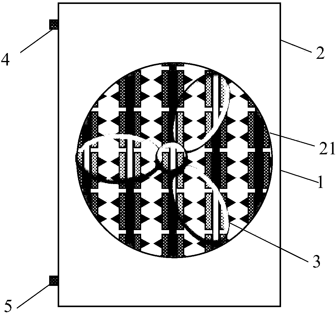
[0025] figure 1 It is a schematic structural diagram of a thermoelectric power generation module based on a flat heat pipe in the present invention, which is mainly composed of a thermoelectric power generation unit 1 , a housing 2 , a fan 3 , a gas interface 4 and a liquid interface 5 . The thermoelectric power generation unit 1 is assembled inside the casing 2 , and the casing 2 is provided with an airflow passage 21 at the front and back, and a fan 3 is provided at the front side of the airflow passage 21 .

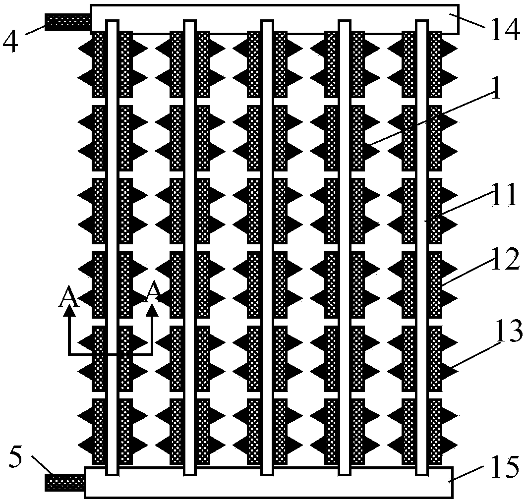
[0026] figure 2 It is a schematic diagram of the structure of the thermoelectric power generation unit 1. The thermoelectric power generation unit 1 is arranged in parallel with several groups of porous parallel flow flat tubes 11 from left to right. The upper and lower ends of the parallel flow flat tube 11 are inserted into the gas header 14 and the liquid...


PUM


Abstract

The invention discloses a thermoelectric generation module based on flat plate heat pipes and a heat pipe circulation waste heat thermoelectric generation system formed by the thermoelectric generation module based on the flat plate heat pipes. The thermoelectric generation module based on the flat plate heat pipes comprises a thermoelectric generation unit, a shell and a fan. Multiple groups of porous parallel flow flat pipes are arranged in the thermoelectric generation unit in parallel. The left and right sides of the porous parallel flow flat pipes are closely provided with thermoelectricgeneration pieces and heat radiation fins in turn. The upper and lower ends of the porous parallel flow flat pipes are inserted into a gas collection pipe and a liquid collection pipe so as to form the integrated thermoelectric generation module. Multiple groups of thermoelectric generation modules and a waste heat pipeline internal heat exchanger, a gas pipeline and a liquid pipeline can form theheat pipe circulation waste heat thermoelectric generation system, and the waste heat in the pipeline can be efficiently transmitted to all the thermoelectric generation modules for power supply through gravity heat pipe circulation. The scheme has the advantages of high generation efficiency, stable voltage, flexible and convenient to design and install and high in expansibility, and standardization, modularization and productization of the thermoelectric generation device can be facilitated.

Description

Technical field: [0001] The invention relates to a thermoelectric power generation module based on a flat heat pipe and a heat pipe cycle waste heat thermoelectric power generation system formed thereof, belonging to the technical field of waste heat recovery and utilization and thermoelectric power generation. Background technique: [0002] With the development of industrialization and the improvement of people's living standards, my country's energy consumption is increasing rapidly, and the problems of energy crisis and environmental pollution are becoming increasingly serious. Reducing energy consumption, improving energy utilization efficiency, and making full use of waste heat have become the only way for my country's energy development. There is a large amount of waste heat in industrial production, building environment construction, and domestic wastewater, and a large amount of cold energy is released in the process of liquefied natural gas gasification. These high-...

Claims


Application Information

Patent Timeline
Patent Type & Authority Applications(China)
IPC IPC(8): H02N11/00
CPCH02N11/002
Inventor 张朋磊张大林武艳荣星月徐旺
Owner NANJING UNIV OF AERONAUTICS & ASTRONAUTICS
Learn More