A high-temperature and high-pressure visualized microscopic oil reservoir chip holder and its use method

A high-temperature, high-pressure, and gripper technology, applied in the direction of workpiece gripping devices, instruments, scientific instruments, etc., can solve the problem of high temperature and high pressure in reservoirs that are difficult to simulate, limit the application of microscopic reservoir chips, and achieve visualization and small volume of grippers. Requirements and other issues, to achieve the effect of rich oil injection scheme, wide application range and wide applicability

Active Publication Date: 2020-06-30
CHINA UNIV OF PETROLEUM (BEIJING)
View PDF10 Cites 1 Cited by
  • Summary
  • Abstract
  • Description
  • Claims
  • Application Information

AI Technical Summary

Problems solved by technology

[0004] At present, the use of microscopic reservoir chips to study reservoir engineering issues in the petroleum field is still in its infancy. Chip fixtures are mainly Luer connectors, which mainly pursue the sealing of the connectors, but it is difficult to simulate the high temperature and high pressure environment of actual reservoirs.
However, the conventional holders used in the field of petroleum engineering are mainly core holders, which are difficult to meet the requirements of visualization and small volume of holders for microscopic reservoir chip displacement experiments, which severely limit the application of microscopic reservoir chips in petroleum Applications in Engineering

Method used


Image

  • A high-temperature and high-pressure visualized microscopic oil reservoir chip holder and its use method
  • A high-temperature and high-pressure visualized microscopic oil reservoir chip holder and its use method
  • A high-temperature and high-pressure visualized microscopic oil reservoir chip holder and its use method

Examples


Embodiment Construction

[0021] The present invention will be described in detail below in conjunction with the accompanying drawings and embodiments.

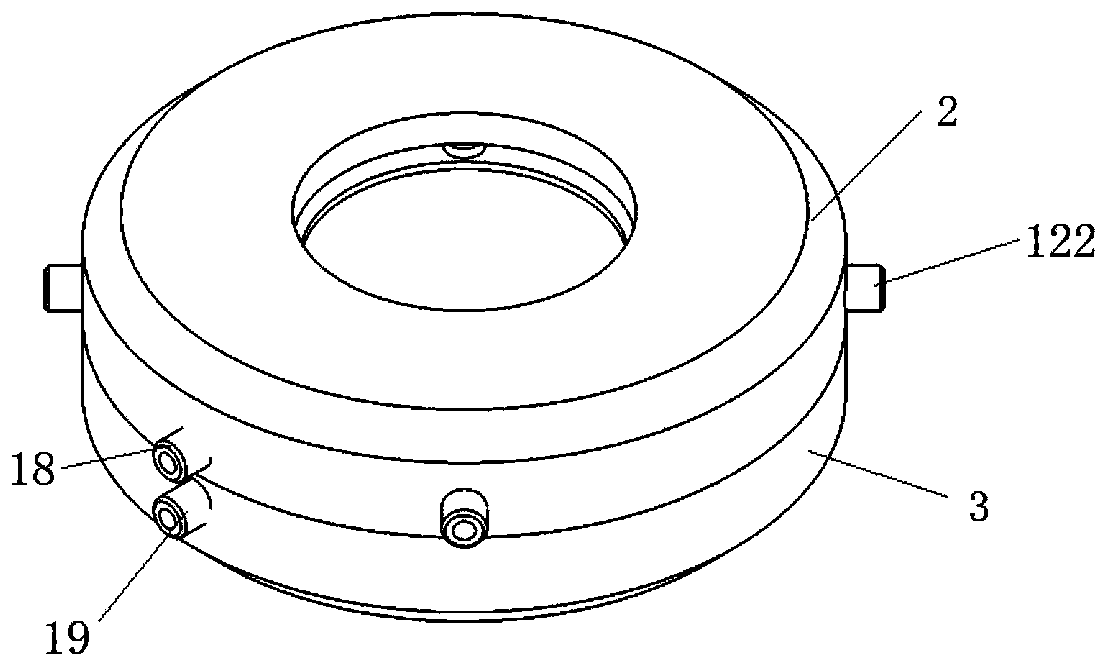
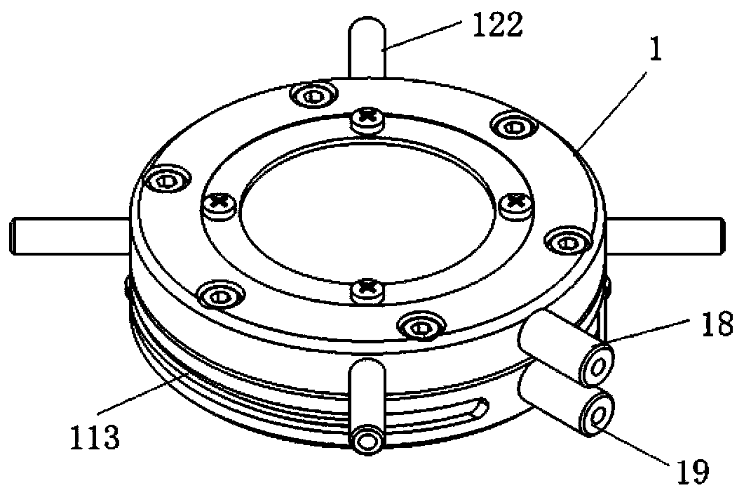
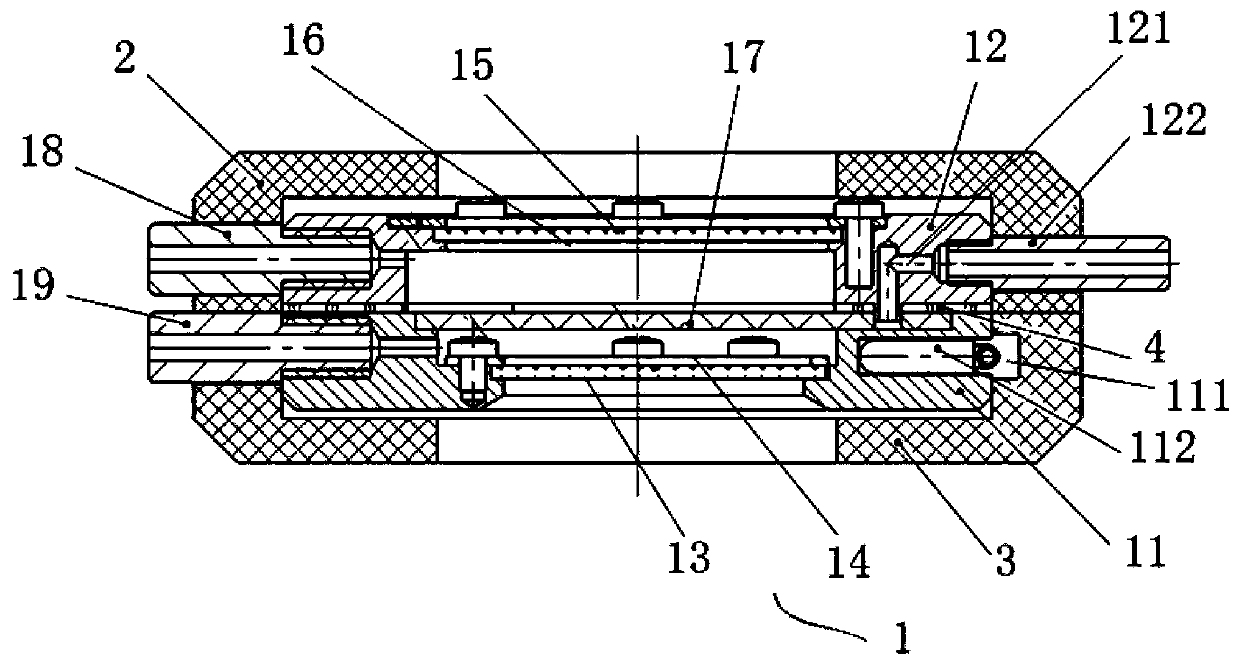
[0022] Such as Figure 1 ~ Figure 3 As shown, the present invention provides a high-temperature and high-pressure visualized microscopic oil reservoir chip holder, which includes a holder body 1 and upper and lower thermal insulation covers 2 and 3 nested outside the holder body 1 . The holder body 1 includes an annular base 11, an annular top cover 12 matching the base 11, a first sapphire lens 13 arranged at the bottom of the base 11, and a first sapphire lens 13 arranged at the bottom of the base 11 for fixing the first sapphire lens 13. The pressure plate 14 , the second sapphire lens 15 arranged on the upper part of the top cover 12 , the second pressure plate 16 arranged on the upper part of the top cover 12 for fixing the second sapphire lens 15 and the microfluidic chip 17 arranged on the upper part of the base 11 . The base 11 and the top co...


PUM


Abstract

The invention relates to a high-temperature and high-pressure visual microscopic oil reservoir chip holder and a use method thereof, wherein the holder is characterized in that the chip holder comprises a holder main body; the holder main body comprises an annular base, an annular top cover, a sapphire lens arranged at the lower part of the base, a press plate for fixing the sapphire lens, anothersapphire lens arranged on the top of the top cover, another press plate for fixing the another sapphire lens, and a microfluidic chip arranged on the base; the base is in blot connection with the topcover, and the microfluidic chip is fixed by an extrusion force between the base and the top cover; a space enclosed by the top cover, the second sapphire lens and the microfluidic chip is an upper seal cavity body, the upper seal cavity body is connected with an upper cavity body connector, and the upper cavity body connector communicates with the outside; a space enclosed by the base, the firstsapphire lens and the microfluidic chip is a lower seal cavity body, the lower seal cavity body is connected with a lower cavity body connector, and the lower cavity body connector communicates withthe outside. The holder can be widely applied in the field of micro-scale effect research.

Description

technical field [0001] The invention relates to the research field of microscale effects in the oil and gas development process, in particular to a high-temperature and high-pressure visualized microscopic oil reservoir chip holder and its use method. Background technique [0002] In the process of oilfield development and production in my country, water flooding is mainly used as the production method. How to evaluate the oil flooding effect and the effects of various chemical reagents used is a problem to be solved at present. In the prior art, there are multi-scale problems in the study of the oil displacement process. During oil field production, the research scope is on the scale of kilometers and meters. When macroscopic physical simulation experiments are carried out in the laboratory, the scale is generally in meters, and most of the thicker cores are used, and only partial conclusions can be drawn by measuring the data of the cores. For the actual effect of the flui...

Claims


Application Information

Patent Timeline
Patent Type & Authority Patents(China)
IPC IPC(8): G01N15/08G01M10/00B25B11/00
CPCB25B11/00G01M10/00G01N15/08
Inventor 李俊键陈石彧于馥玮苏航孟凡乐刘洋苏海婷
Owner CHINA UNIV OF PETROLEUM (BEIJING)
Why Eureka
Try Eureka