
Centrifugal double-rotating super-gravity flue gas purification device

A flue gas purification and supergravity technology, which is applied in gas treatment, separation methods, and dispersed particle separation, etc., can solve the problems of exhaust gas blockage in supergravity, low static and dynamic pressure of flue gas, and difficulty in passing through packing, etc., and achieve high-speed rotation The effects of less vibration, low rotational energy consumption and high desulfurization efficiency

Active Publication Date: 2018-02-23
广州市浩立生物科技有限公司
View PDF8 Cites 2 Cited by
  • Summary
  • Abstract
  • Description
  • Claims
  • Application Information

AI Technical Summary

Problems solved by technology

However, the static pressure and dynamic pressure of the flue gas at the ventilation outlet are still low, which makes it difficult for it to pass through the thick packing and cause the exhaust gas in the supergravity to block

Method used


Image

  • Centrifugal double-rotating super-gravity flue gas purification device
  • Centrifugal double-rotating super-gravity flue gas purification device
  • Centrifugal double-rotating super-gravity flue gas purification device

Examples


Embodiment 1

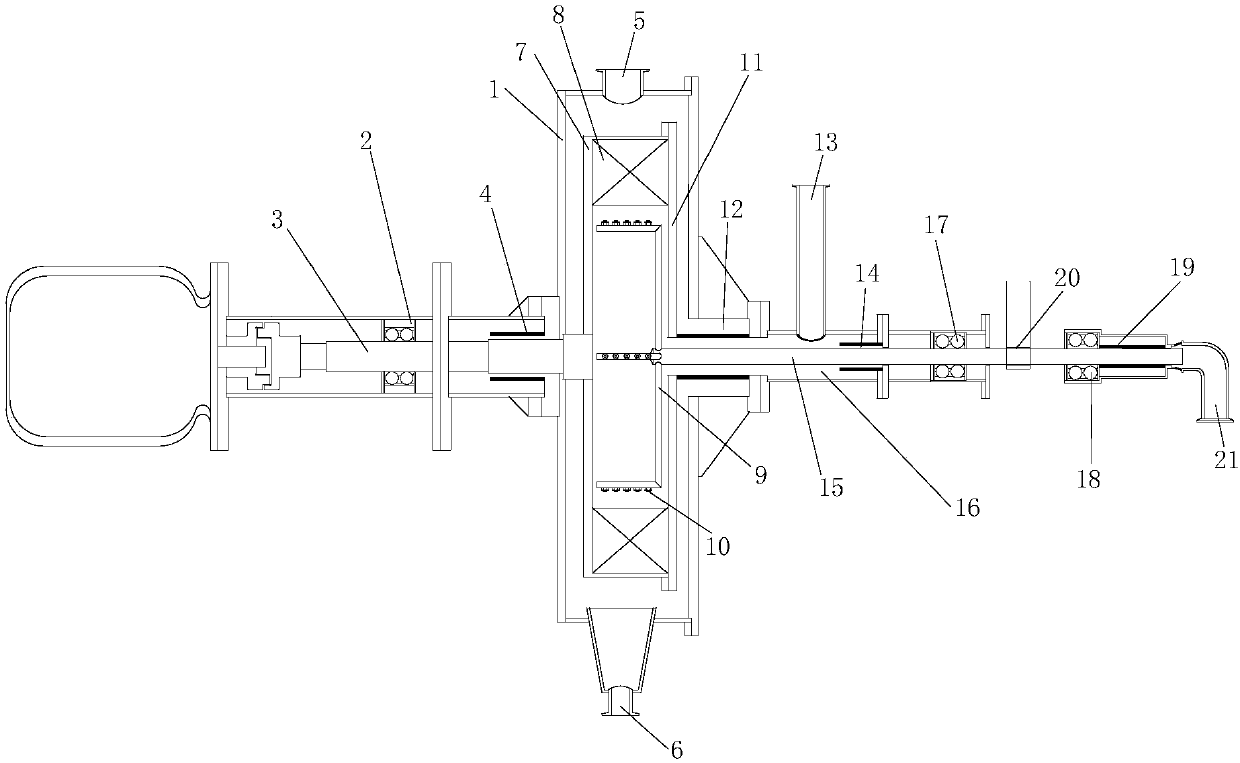
[0022] Such as figure 1 As shown, the present invention is a centrifugal double-rotation supergravity flue gas purification device, comprising a housing 1 provided with a gas inlet 5, a gas outlet 13 and a liquid outlet 6, the middle part of the housing 1 is a central rotating reaction zone, and the gas The inlet 5 and the gas outlet 13 are separated. In this embodiment, the gas inlet 5 is set at the top of the central rotating reaction zone, and the liquid outlet 6 is set at the bottom of the central rotating reaction zone. The central rotating reaction zone communicates with the gas outlet 13 through the gas channel 16 .

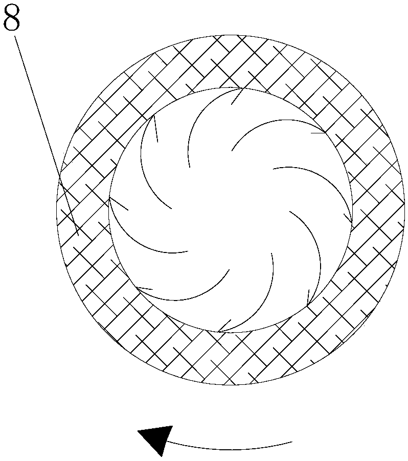
[0023] The central rotating reaction zone is provided with a rotating disc 7 and packings 8 annularly distributed on the rotating disc 7. In the middle of the inner ring of the packing 8, a hollow multi-directional rotating rocker arm 9 and a multi-directional rotating rocker arm 9 are provided. Each liquid spray head 10, the rotating disc 7 and the mult...

Embodiment 2

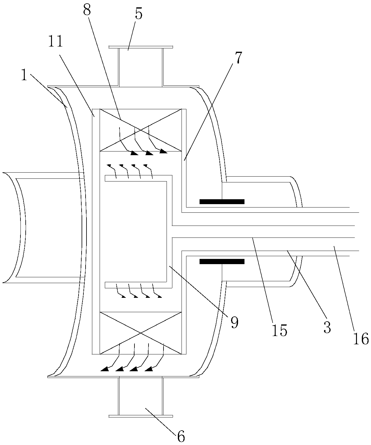
[0031] Such as image 3 As shown, in this embodiment, the rotating shafts of the rotating disk 7 and the multi-directional rotating rocker arm 9 are respectively arranged in the same direction. At this time, both the first rotating shaft 15 and the second rotating shaft 3 are hollow, and the first rotating shaft 15 and the second rotating shaft 3 are concentric and arranged inside the second rotating shaft 3 . The gap between the first rotating shaft 15 and the second rotating shaft 3 forms a gas channel 16 .

[0032] Others are the same as embodiment 1.


PUM


Abstract

The invention discloses a centrifugal double-rotating super-gravity flue gas purification device, which comprises a shell provided with a gas inlet and a gas outlet; a central rotation reaction area is arranged in the middle of the shell, and the gas inlet and the gas outlet are separated from each other by means of the central rotation reaction area; the centrifugal double-rotating super-gravityflue gas purification device is characterized in that the central rotation reaction area is internally provided with a rotating disc and filler distributed on the rotating disc in a ring shape; a multi-direction rotating rocker arm and a plurality of liquid spray nozzles arranged on the multi-direction rotating rocker arm are arranged in the middle of an inner ring of the filler; the rotating discand the multi-direction rotating rocker arm are respectively connected with different rotating shafts and are driven to rotate separately by the respectively rotating shafts. Due to centrifugal liquid throwing, a liquid phase has a certain linear velocity when being thrown out, thus more easily crawling to the filler; furthermore, the gas-liquid countercurrent contact washing and absorption effect is more obvious, and the desulfurization efficiency of the mixture of atmospheric pressure desulfurization fluid and flue gas is higher; therefore, the centrifugal double-rotating super-gravity fluegas purification device can be widely applied to flue gas desulfurization.

Description

technical field [0001] The invention relates to the field of flue gas desulfurization, in particular to an enhanced gas-liquid mass transfer reaction device. Background technique [0002] The high-gravity rotating bed device uses a high-speed rotating rotor to drive the packing to rotate at a high speed, so that the reaction liquid attached to the packing has centrifugal acceleration. Compared with the traditional tens of meters high chimney, it greatly improves the mass transfer intensity and greatly reduces the size of traditional mass transfer equipment, which is a breakthrough development for traditional mass transfer equipment. [0003] Most of the high-gravity rotating bed devices currently used in industry are dynamic and static structures, that is, the liquid-phase spray device is static and fixed, and the filler rotates around the liquid-phase spray head. Under the condition of constant rotation speed, the most effective way to improve the mass transfer effect of t...

Claims


Application Information

Patent Timeline
Patent Type & Authority Applications(China)
IPC IPC(8): B01D53/75B01D53/78B01D53/50B01D53/76B01D53/56
CPCB01D53/50B01D53/507B01D53/56B01D53/75B01D53/76B01D53/78B01D2258/0283
Inventor 朱力毛忠冯志豪温雄辉梁振明
Owner 广州市浩立生物科技有限公司
Learn More