Fiber-sensing-based safety detection method for oil and gas pipeline

A technology for safety detection of oil and gas pipelines, applied in measuring devices, measuring ultrasonic/sonic/infrasonic waves, instruments, etc., can solve the problem of the minimum integration time limiting spatial resolution, etc., and achieve easy deployment, improved resolution, and high signal-to-noise ratio Effect

Inactive Publication Date: 2018-02-23
UNIV OF ELECTRONICS SCI & TECH OF CHINA
View PDF10 Cites 3 Cited by
  • Summary
  • Abstract
  • Description
  • Claims
  • Application Information

AI Technical Summary

Problems solved by technology

However, the pulse width of the incident laser and the minimum integration time of the photodetector greatly limit the spatial resolution of this type of system.

Method used


Image

  • Fiber-sensing-based safety detection method for oil and gas pipeline
  • Fiber-sensing-based safety detection method for oil and gas pipeline
  • Fiber-sensing-based safety detection method for oil and gas pipeline

Examples


Embodiment 1

[0026] Embodiment 1: A distributed optical fiber sensing system based on a single U-shaped structure:

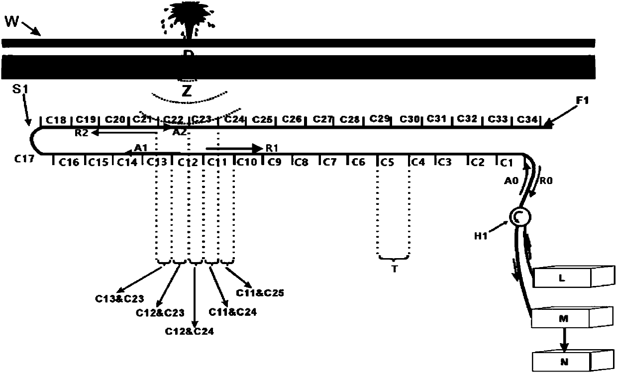
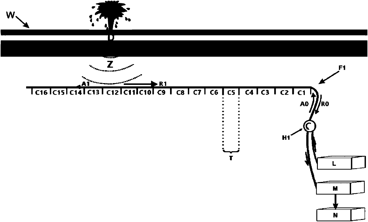
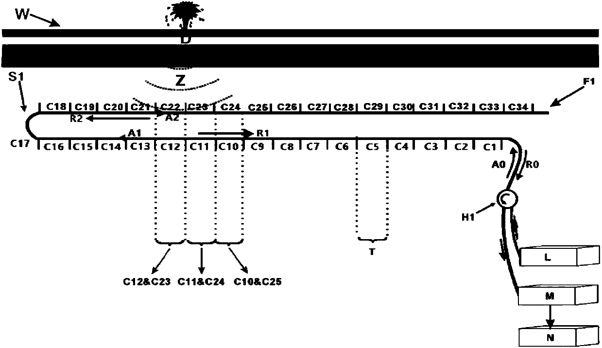
[0027] figure 1 A distributed optical fiber sensing system based on a single U-shaped structure is demonstrated. A single U-shaped optical fiber F1 is buried in the soil below the surface close to the oil and gas pipeline to ensure that the sensing optical fiber maintains high sensitivity to vibration. The vibration signal (Z1) caused by man-made damage or pipeline aging leakage will act indirectly on the sensing fiber to change the transmission and scattering characteristics of the sensing fiber. According to the pulse width (T) of the pulsed laser used in the system, the sensing fiber is sequentially divided into continuous channels (C1, C2, C3...C34) with a length of (T / 2) from the laser incident end, and the incident pulsed laser A0, A1 passes through the circulator to extend the forward transmission of the optical fiber, and the backscattered light R1 and R2 generated ...

Embodiment 2

[0039] Embodiment 2: Distributed optical fiber sensing system based on 3U structure:

[0040] like Figure 5 As shown, on the basis of the above-mentioned single U interleaved distribution structure, a 3U optical fiber distribution structure can be further adopted, in which the corresponding channels have a dislocation of 1 / 4 channel length. 5-A represents the vibration signal (Z1) caused by man-made damage or pipeline leakage, and 5-B represents the backscattered light signal waveform sampled by channels C56, C57, C58, C59, C60, and C61 when the optical pulse is transmitted in the optical fiber , 5-C is the backscattered light signal waveform sampled by channels C50, C49, C48, C47, C46, ​​and C45 when the optical pulse is transmitted in the optical fiber, 5-D is the channel C22, The backscattered light signal waveforms sampled by C23, C24, C25, and C26, 5-E is the backscattered light signal waveform sampled by channels C13, C12, C11, C10, and C9 when the optical pulse is tra...


PUM


Abstract

Disclosed in the invention is a fiber-sensing-based safety detection method for an oil and gas pipeline. U-shaped distributed sensing fibers are arranged along an oil and gas pipeline. Each U-shaped distributed sensing fiber has the following structure: the sensing fiber for detecting an intrusive vibration source caused by pipe leakage is arranged to have a U-shaped fiber structure with two parallel sides; the sensing fiber is divided into a series of continuous sub channels with equal lengths by starting with a starting end, wherein the length of each sub channel is half of the incident pulse laser line width of the sensing fiber; the sub channels at the two sides, parallel to each other, of the U-shaped fiber structure are staggered; and each two corresponding sub channels at the two sides form one virtual sensing channel group. A series of pulse laser is sent continuously at one end of each U-shaped distributed sensing fiber and backscattering laser generated by each virtual sensing channel group is received at a sending end simultaneously. On the basis of the backscattering laser, positioning of an intrusive vibration source caused by pipe leakage is realized and thus the pipeleakage location is obtained. The detection way is simple; reliability is high; and the anti-electromagnetic interference performance is good.

Description

technical field [0001] The invention relates to the fields of optical fiber sensing, optical fiber communication and signal processing, in particular to optical fiber sensing and signal processing technologies. Background technique [0002] As the most efficient way to transport oil and gas resources, pipeline transmission has been widely used. However, in recent years, pipeline leakage incidents caused by drilling oil theft, natural disasters and pipeline aging [0003] Repeatedly, the economy and the environment have paid a huge price. Therefore, the safety monitoring of oil and gas pipelines [0004] Work is particularly important. In recent years, optical fiber sensing technology has developed rapidly. It has the advantages of anti-electromagnetic interference, high sensitivity, and large dynamic range, and has been applied in the field of oil and gas pipeline safety monitoring. When events such as vibration or stress caused by oil and gas pipeline leakage events act...

Claims


Application Information

Patent Timeline
Patent Type & Authority Applications(China)
IPC IPC(8): G01H9/00
CPCG01H9/004
Inventor 张扬张茜吴宇刘宗豪
Owner UNIV OF ELECTRONICS SCI & TECH OF CHINA
Why Eureka
Try Eureka