II-shaped groove antenna

An I-shaped slot and antenna technology, applied in the direction of the connection of the antenna grounding switch structure and the structure of the radiating element, can solve the problems that the input impedance cannot be completely matched, increase the design complexity, affect the frequency characteristics, etc., and achieve flat in-band gain. , Simple structure, high isolation effect

Pending Publication Date: 2018-02-23
SOUTH CHINA UNIV OF TECH
View PDF9 Cites 3 Cited by
  • Summary
  • Abstract
  • Description
  • Claims
  • Application Information

AI Technical Summary

Problems solved by technology

[0003] At present, duplex antennas are widely used in wireless communication systems. If the antenna and duplexer are designed separately, the introduction of matching circuits will increase the complexity of the design while increasing the size of the device; secondly, due to the antenna and duplexer Due to the different bandwidths of duplexers, their input impedances usually cannot be completely matched, which directly affects the frequency characteristics, so this requires a joint design

Method used


Image

  • II-shaped groove antenna
  • II-shaped groove antenna
  • II-shaped groove antenna

Examples


Embodiment

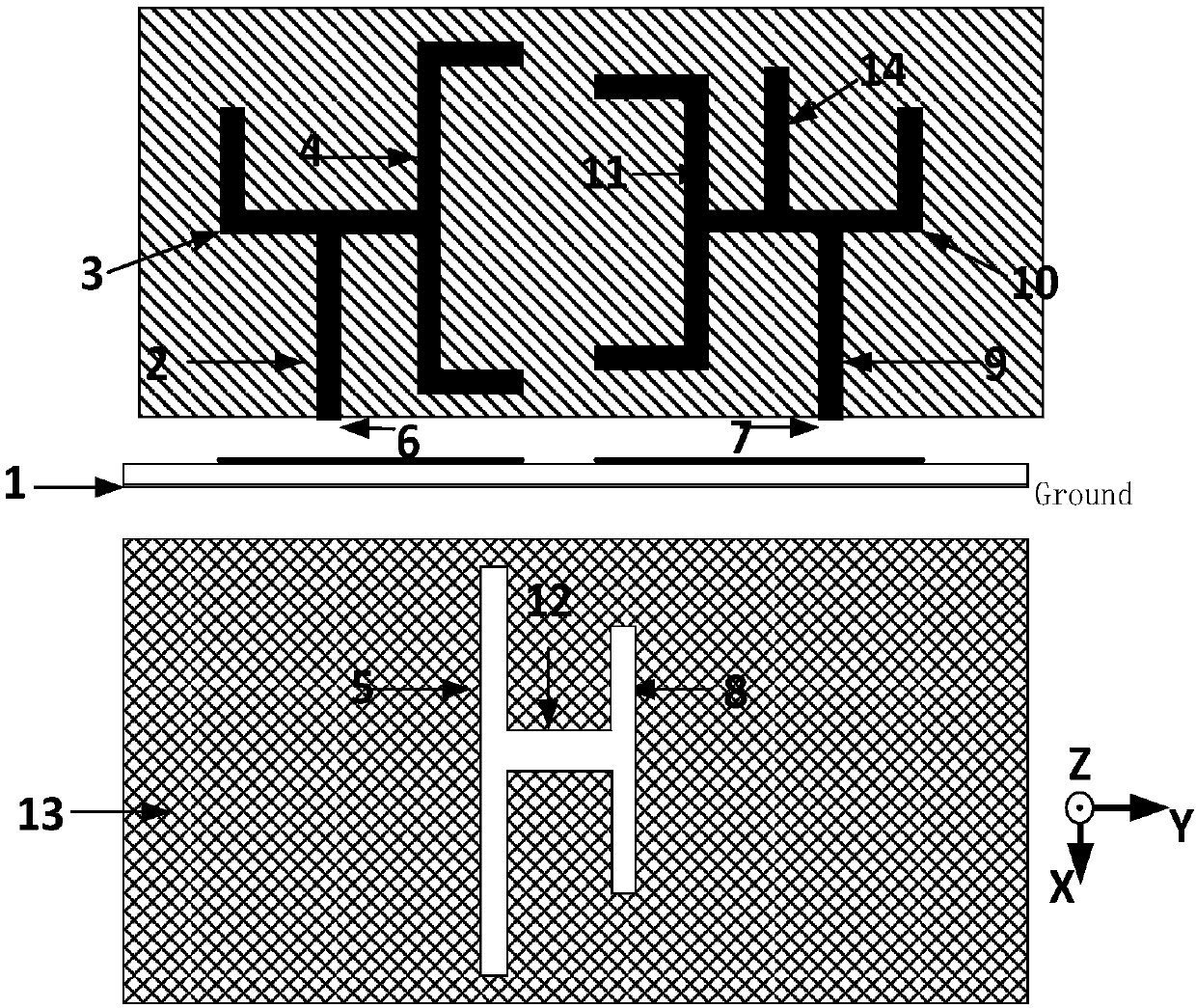
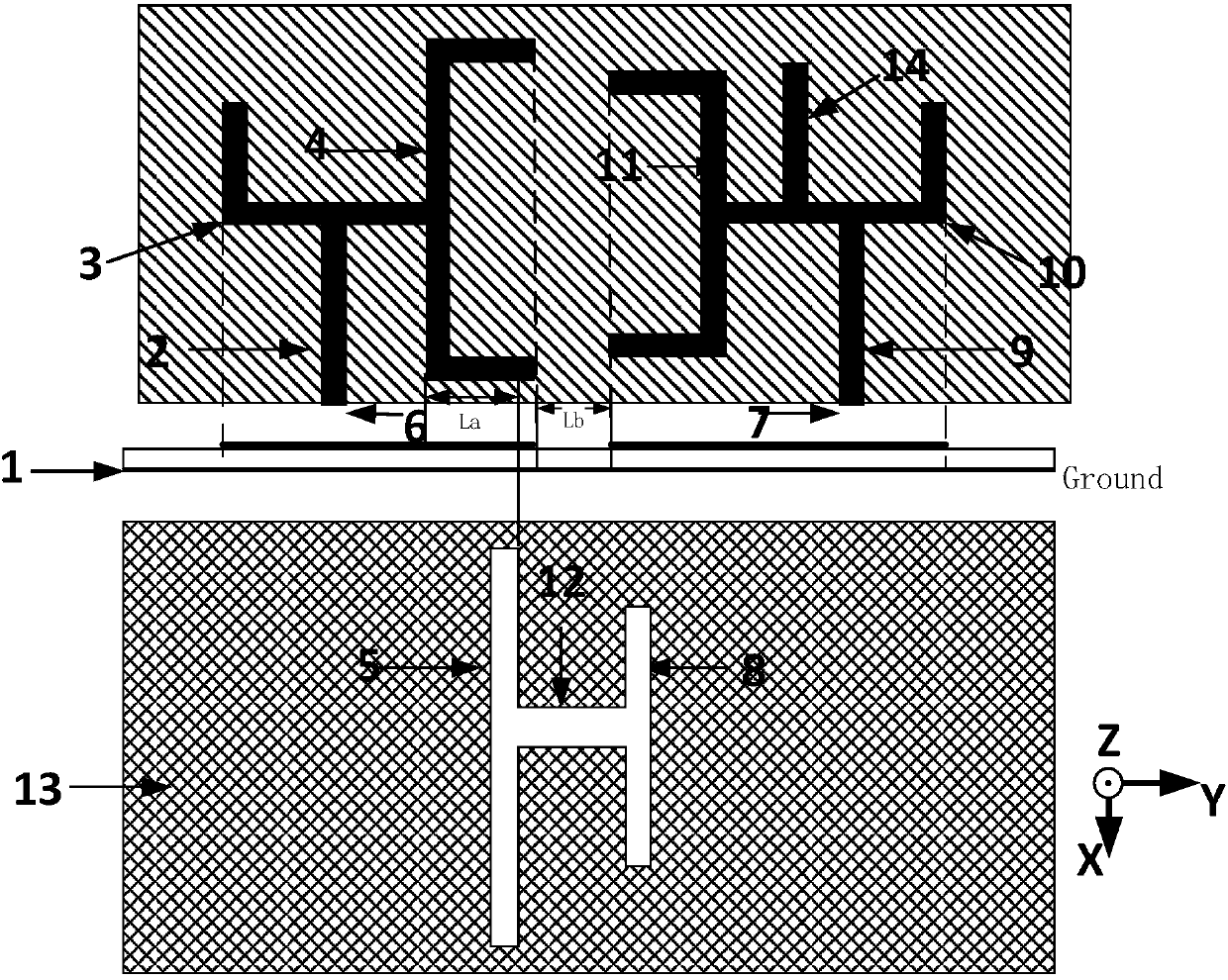
[0029] This embodiment provides a duplex I-shaped slot antenna, the general schematic diagram is as follows figure 1 As shown, it includes a dielectric substrate (1), a feed network composed of microstrip lines on the upper surface of the dielectric substrate (1), a floor (13) and an "I" shaped groove located on the lower surface of the floor (13). The electrical network includes a transmitting channel feeding network and a receiving channel feeding network. The transmission channel feed network is located on the left part of the upper surface of the dielectric substrate (1), including a C-type microstrip line (4) of the transmission channel, an L-shaped open-circuit stub line (3) of the transmission channel connected in the middle position, and a pair of transmission channels. Channel L-shaped open-circuit stub line (3) carries out end-coupling feeding channel feeding microstrip line (2), and the transmitting channel feeding microstrip line (2) is connected to the transmittin...


PUM


Abstract

The invention discloses an II-shaped groove antenna. The II-shaped groove antenna comprises a medium substrate, a feed network which is arranged on the medium substrate and consists of microstrip lines, a ground plate and an I-shaped groove formed in the lower surface of the ground plate. The feed network comprises an emission channel feed network arranged on the left part of the upper surface ofthe medium substrate and a receiving channel feed network arranged on the right side of the upper surface of the medium substrate. The emission channel feed network comprises a C type microstrip line,an L type open-circuit branch line connected to the middle position of the C type micro-strip line and a feed micro-strip line performing end coupling feeding on the L type open circuit branch line;the feed micro-strip line is connected to an emission port; the receiving channel feed network comprises the C type micro-strip line, the L type open circuit branch line arranged in the middle position of the C type micro-strip line, an open circuit branch line connected to the L type open circuit branch line, a feed micro-strip line performing end coupling feeding on the L type open circuit branch line; the feed micro-strip line is connected to the receiving port; and the I-shaped groove consists of three rectangle grooves of different sizes which form in an I shape.

Description

technical field [0001] The invention relates to the technical field of wireless communication, in particular to a duplex I-shaped slot antenna. Background technique [0002] Antennas are devices used to transmit and receive electromagnetic waves and are widely used in radio communication systems. Duplex communication is divided into half-duplex communication and full-duplex communication. The half-duplex system allows two-way data transmission between two devices, but not at the same time. Therefore, only one device is allowed to send data at the same time. If the other If a device wants to send data, it needs to wait for the device that originally sent the data to complete the transmission before processing. Walkie-talkies use a half-duplex system. A full-duplex system allows two-way data transmission between two devices at the same time. Ordinary telephones and mobile phones are full-duplex systems, because you can also hear the other party's voice while speaking. [00...

Claims


Application Information

Patent Timeline
Patent Type & Authority Applications(China)
IPC IPC(8): H01Q1/36H01Q1/50
CPCH01Q1/36H01Q1/50
Inventor 胡玮谢泽明
Owner SOUTH CHINA UNIV OF TECH
Why Eureka
Try Eureka