A ccpp system bypass gas temperature reduction and pressure reduction and waste heat recovery equipment

A waste heat recovery equipment, temperature reduction and pressure reduction technology, applied in mechanical equipment, piping systems, gas/liquid distribution and storage, etc., can solve the problems of low cooling efficiency, large metal heat exchange area, etc., to reduce labor costs, Enhanced heat transfer efficiency and fast processing speed

Active Publication Date: 2019-02-19
HUATIAN ENG & TECH CORP MCC
View PDF9 Cites 0 Cited by
  • Summary
  • Abstract
  • Description
  • Claims
  • Application Information

AI Technical Summary

Problems solved by technology

Indirect cooling requires a large metal heat transfer area, because the heat transfer rate is limited by the heat transfer rate of the metal heat transfer area, so the cooling efficiency is not high

Method used


Image

  • A ccpp system bypass gas temperature reduction and pressure reduction and waste heat recovery equipment

Examples


Embodiment 1

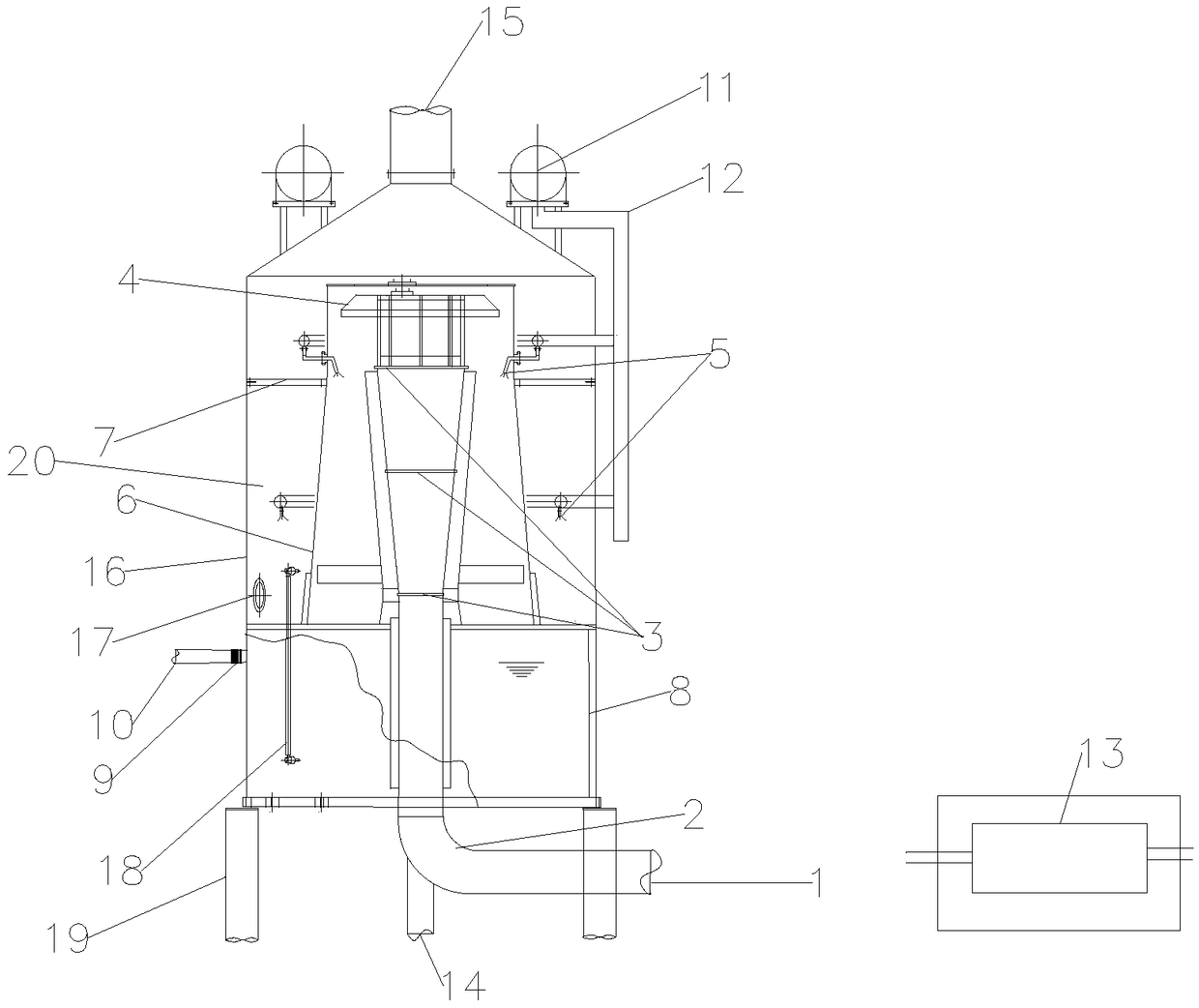
[0027] Such as figure 1 As shown, a CCPP system bypass gas temperature reduction and pressure reduction and waste heat recovery equipment includes a base 19, an equipment shell 16 above the base 19, and a gas pipeline 2. The top of the equipment shell 16 is provided with a gas outlet 15, which The lower part is a sump 8, and the outer side of the sump 8 is connected with a hot water pipe 10; above the sump 8, a diffusion pipe 6 is arranged; a gas channel 20 is formed between the diffusion pipe 6 and the equipment casing 16, and a Mist eliminator 7, the bottom end of this diffuser pipe 6 communicates with sump 8 and gas channel 20 respectively; Described gas pipe 2 enters equipment shell 16 from the bottom end of equipment shell 16 and extends in the diffuser pipe 6, and it is in One end outside the equipment shell 16 has a gas pipeline inlet 1, and a number of decompression orifice plates 3 are arranged in the pipe, and the decompression orifice plate 3 here can be a porous de...

Embodiment 2

[0035] Such as figure 1 As shown, on the basis of Example 1, the gas pipeline 2 and the diffusion pipeline 6 are made of anti-corrosion materials, which can effectively prevent gas and impurities from corroding each pipeline and affecting the normal operation of the equipment.

Embodiment 3

[0037] Such as figure 1 As shown, the walls of gas pipeline 2 and diffusion pipeline 6 described in Example 1 are all provided with anti-corrosion coatings, which can effectively prevent gas and impurities from corroding each pipeline and affect the normal operation of the equipment.


PUM


Abstract

The invention discloses bypass coal gas temperature decreasing, pressure reducing and afterheat recovering equipment for a CCPP (Combined Cycle Power Plant) system. The bypass coal gas temperature decreasing, pressure reducing and afterheat recovering equipment for the CCPP system comprises a base, an equipment shell, a coal gas pipeline and a cooling water circulating pump; a coal gas outlet is formed in the top of the equipment shell; a water collecting tank is arranged at the bottom of the equipment shell; a hot water pipeline is arranged on the outer side of the equipment shell; a dispersing pipeline is arranged above the water collecting tank; the dispersing pipeline forms a coal gas channel with the equipment shell, and a demister is arranged; the bottom end of the dispersing pipeline communicates with each of the water collecting tank and the coal gas channel; the coal gas pipeline enters from the bottom end of the equipment shell and extends into the dispersing pipeline; a coalgas pipeline inlet is formed in the end, out of the equipment shell, of the coal gas pipeline; a plurality of pressure reducing porous plates are arranged in the coal gas pipeline; a flow guide stopplate is arranged above the coal gas pipeline outlet; a top water tank is arranged at the top end out of the equipment shell and is connected with a cooling water pipeline; and a plurality of coolingwater spraying nozzles which are connected with the cooling water pipeline are arranged in the dispersing pipeline. The bypass coal gas temperature decreasing, pressure reducing and afterheat recovering equipment for the CCPP system integrates temperature decreasing, pressure reducing and afterheat recovering; the equipment volume is reduced; the equipment cost is reduced; the maintenance labour intensity is reduced; the operating cost is reduced; and the practicability is high.

Description

technical field [0001] The invention belongs to the technical field of energy and environmental protection, and in particular relates to a CCPP system bypass gas temperature reduction and pressure reduction and waste heat recovery equipment. Background technique [0002] The CCPP technology (gas-steam combined cycle power generation) that burns blast furnace gas has a gas-to-electricity conversion rate of 40% to 50%, which is about 70% higher than conventional boiler steam power generation. It is widely used by many domestic and foreign iron and steel enterprises in recent years. The use of technology has broad prospects. As one of the process equipment of blast furnace gas CCPP unit, the function of the gas bypass decompression equipment is to ensure the safe return of high-pressure gas from the compressor outlet to the gas supply pipeline during partial load, normal shutdown or emergency. It is necessary to decompress the medium-pressure gas at 450-500°C to low pressure, ...

Claims


Application Information

Patent Timeline
Patent Type & Authority Patents(China)
IPC IPC(8): C21B7/22C21B5/06F17D3/01
CPCC21B5/06C21B7/22F17D3/01Y02E20/16Y02P10/20Y02P10/25
Inventor 邓尘姚群冯红翠张学超邵帅陈璐周华
Owner HUATIAN ENG & TECH CORP MCC
Why Eureka
Try Eureka